UAE: +971 6 55 222 55 | USA: +1 (833) VSAT 123


In professional satellite communications, maintaining signal continuity is essential for network reliability, operational efficiency, and service availability. Unexpected failures involving Low Noise Blocks (LNBs), upconverters, downconverters, or other RF components can interrupt signal delivery and require immediate intervention. The Quintech RFS 2150 RF Sensing Redundancy Switch addresses this challenge by automatically detecting the loss of a primary RF signal and switching to a secondary backup signal.
Manufactured by Quintech Electronics & Communications, the RFS Series is designed for professional RF redundancy applications, scheduled maintenance, and remote installations. Operating across the 950–2150 MHz L-band frequency range, the RFS 2150 provides adjustable RF detection thresholds, manual override functionality, alarm signaling, and optional remote control. These capabilities make it a practical solution for satellite ground stations, teleport facilities, and RF systems where service interruptions must be minimized.
Available through VSATPlus, the Quintech RFS 2150 is suitable for organizations seeking dependable RF switching equipment for satellite communication infrastructure.
The Quintech RFS 2150 is an RF-sensing redundancy switch that monitors a primary RF signal and provides the ability to switch to a secondary signal when the primary signal is lost. Instead of relying exclusively on manual intervention, the system uses RF signal detection to support automatic backup switching.
This functionality is especially useful in installations where a loss of signal can interrupt service or require costly emergency maintenance. By providing a secondary signal path, the RFS 2150 helps operators implement a redundancy strategy for compatible RF equipment.
The manufacturer identifies failed LNBs, upconverters, downconverters, unmanned facilities, and fiber-link backup systems as potential applications. The datasheet also highlights scheduled maintenance as an important use case, allowing operators to work on compatible equipment while using a backup signal path.

The RFS 2150 detects the presence of the primary RF signal and can switch to a secondary signal when the primary is lost.
This feature supports continuity in systems where a reliable RF feed is essential. It can reduce dependence on immediate manual intervention and help operators manage certain signal failures more efficiently.
Key benefits:
Automatic switching depends on correct system configuration, a suitable backup signal, and the configured RF detection threshold.
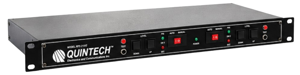
The RFS 2150 features an adjustable detection level from -60 dBm to -20 dBm. Operators can adjust the threshold using the front-panel up/down push buttons.
This flexibility allows the detection setting to be adapted to the RF levels present in the installation. Correct threshold selection is important because the switch must distinguish between an acceptable primary signal and a signal condition that should trigger backup switching.
Key benefits:
In addition to automatic RF sensing, the RFS 2150 includes a front-panel slide switch for manual override.
This allows an operator to select the required signal path during installation, troubleshooting, testing, or scheduled maintenance. Manual control complements automatic switching by giving technical personnel a direct way to manage the redundancy path when necessary.
The RFS Series supports a Form C contact-closure alarm, with a rear-panel barrier strip providing the interface for summary alarm and remote override functions. An optional RS-232 DB-9 interface enables remote control on compatible models. The datasheet specifically identifies the RFS 2150/2 with optional serial control for RS-232 operation.
These capabilities help integrate the switch into broader monitoring and control arrangements.
Key benefits:
Important: RS-232 remote control is an option and should be confirmed for the selected model.
Maintaining satellite communication equipment often requires testing, replacement, or servicing of components within the RF signal chain. The RFS 2150 supports redundancy arrangements that can facilitate maintenance by allowing a compatible backup path to be selected while work is carried out on the primary path.
This is particularly useful in systems where service availability is important. However, uninterrupted operation depends on the backup equipment, signal path, and overall system design.
The RFS 2150 uses a compact 1RU chassis designed for installation in a standard 19-inch equipment rack.
Its rack-mount format makes it suitable for professional satellite ground stations, teleport facilities, and centralized RF equipment rooms where efficient use of rack space is important.

The Quintech RFS 2150 can support a range of professional RF redundancy applications.
Ground stations rely on RF equipment to receive and distribute satellite signals. A redundancy switch can provide a backup path when the primary RF signal is lost, helping operators reduce the impact of certain equipment failures.
Teleport operators manage complex satellite communication infrastructure where service availability is important. The RFS 2150 can form part of a redundancy arrangement involving compatible RF components and backup signal paths.
Low Noise Blocks are critical components in satellite receive systems. The RFS 2150 is identified by the manufacturer as suitable for redundancy applications involving failed LNBs. A properly configured backup LNB and signal path can help maintain reception if the primary path fails.
Upconverters and downconverters perform important frequency-conversion functions in satellite communication systems. The RFS 2150 can support redundancy arrangements designed to switch between primary and secondary signal paths when compatible equipment fails.
At unattended sites, sending technicians to investigate every signal interruption can increase maintenance time and operational costs. Automatic RF sensing and backup switching can help reduce the need for immediate emergency restoration visits.
The manufacturer also identifies 1:1 redundancy for fiber-link backup as an application. The switch can be considered for compatible systems where two RF signal paths are available and the system design supports the required switching arrangement.
The following table summarizes the published specifications for the Quintech RFS 2150 RF Sensing Redundancy Switch.
| Specification | Details |
|---|---|
| Product Series | Quintech RFS Series |
| Model | RFS 2150 |
| Product Type | RF Sensing Redundancy Switch |
| Operating Frequency | 950–2150 MHz |
| Detected Frequency | 950–2150 MHz |
| Impedance | 75 Ω or 50 Ω |
| Adjustable RF Detection Level | -60 dBm to -20 dBm |
| Insertion Loss | 2.5 dB ±1 dB |
| Frequency Response | ±1.0 dB |
| Isolation | 40 dB |
| Return Loss | 12 dB |
| Inputs/Outputs | Dual 2×1 |
| Automatic Switching | Switches to secondary signal upon loss of primary RF signal |
| Manual Override | Front-panel slide switch |
| Threshold Adjustment | Front-panel up/down push buttons |
| Alarm Interface | Form C contact closure |
| Remote Override | Available through contact-closure interface |
| Remote Serial Control | Optional RS-232; confirm model configuration |
| RF Connector Options | F-type or BNC; 75 Ω or 50 Ω, depending on configuration |
| Power Requirements | 100–240 VAC, autoranging |
| Power Frequency | 50/60 Hz |
| Power Consumption | 21 W |
| Rack Format | 1RU |
| Dimensions | 1.75″ H × 19″ W × 14″ D |
| Available Configurations | Single or dual configuration |
| Optional LNB Power | 18–24 VDC |
Specifications may vary depending on connector type and configuration. Confirm the exact model and optional features before ordering.
When selecting an RF redundancy switch, it is important to consider more than its switching function.
Operating frequency: The 950–2150 MHz range covers the L-band frequencies specified for this model. The connected equipment must operate within the supported range.
Insertion loss: The published insertion loss is 2.5 dB ±1 dB. This should be included in the system’s RF link budget to ensure adequate signal levels throughout the signal chain.
Isolation: The specified 40 dB isolation describes the separation between signal paths under the manufacturer’s test conditions. This parameter is relevant when evaluating the switch for a particular redundancy arrangement.
Return loss: The published 12 dB return loss specification helps engineers assess impedance matching and potential signal reflections.
Adjustable detection level: The -60 dBm to -20 dBm detection range allows the RF sensing threshold to be set according to the intended signal conditions. The correct threshold should be selected and tested during commissioning.
These parameters should be evaluated alongside the characteristics of the connected LNBs, converters, receivers, and backup signal sources.
Before integrating the RFS 2150 into a satellite communication system, engineers should verify several requirements.
Correct configuration and testing help ensure that the switch operates as expected within the wider RF system.

The Quintech RFS 2150 RF Sensing Redundancy Switch provides automatic RF signal detection, backup switching, adjustable thresholds, manual override, and alarm functionality in a compact rack-mount design. These features make it a useful component for satellite ground stations, teleport facilities, remote RF installations, and other applications where primary signal failure must be managed efficiently.
At VSATplus, customers can source professional satellite communication and RF equipment for their network infrastructure. Our team can help you review connector options, confirm the required configuration, and determine whether optional LNB power or serial control is needed for your application.
Whether you are upgrading an existing redundancy system or designing a new installation, selecting the correct switching equipment is an important step toward improving operational resilience.

Looking for the Quintech RFS 2150 RF Sensing Redundancy Switch?
Contact VSATPlus for pricing, availability, and configuration assistance.
Request a quote from VSATPlus today and find the right Quintech RF redundancy solution for your satellite communication system.