UAE: +971 6 55 222 55 | USA: +1 (833) VSAT 123

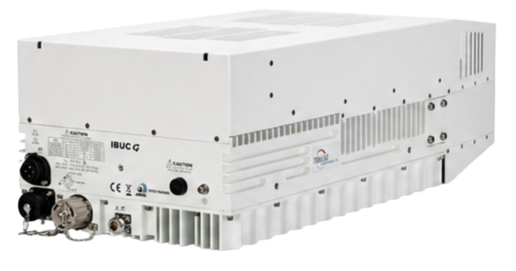
In professional satellite communications, the outdoor RF subsystem plays a critical role in determining the overall performance, reliability, and scalability of a VSAT network. When a network must support multiple carriers, higher throughput, long-distance transmission, and demanding link budgets, the choice of Block Upconverter (BUC) becomes particularly important.
The Terrasat IBUC G Ku-Band 150W / 200W is a high-power outdoor BUC designed specifically for multicarrier satellite applications. According to the supplied manufacturer documentation, the IBUC G is available in 150W and 200W output-power configurations and supports multiple Ku-band frequency plans, high gain, adjustable attenuation, automatic level control, external frequency reference, remote monitoring and control, and optional cyber-hardened management capabilities.
For satellite operators, teleport providers, network integrators, broadcasters, enterprise VSAT operators, and organizations requiring high-power Ku-band transmission, the IBUC G provides a combination of RF performance and network-management capabilities designed for demanding deployments.
VSATPlus offers the Terrasat IBUC G Ku-Band 150W / 200W for customers requiring high-power multicarrier satellite transmission solutions. Contact VSATPlus for pricing, availability, configuration, and ordering.
The IBUC G is an Intelligent Block Upconverter designed to convert an L-band intermediate-frequency signal into a Ku-band RF transmission signal while providing substantial RF amplification.
In a typical satellite transmission chain, the modem or IF equipment produces an L-band signal. That signal travels through the intermediate-frequency link toward the outdoor RF equipment. The BUC then performs two fundamental functions:
The IBUC G extends this basic BUC architecture with features intended for professional network environments, including adjustable attenuation, automatic level control, output-power monitoring, external 10 MHz reference support, Ethernet-based management, serial interfaces, and optional cyber-hardened functionality.
The supplied documentation specifically identifies the product as:
“Ku-Band 150W | 200W IBUC G for Multicarrier Application.”
This multicarrier orientation is important because the BUC is designed to maintain appropriate linearity and noise-performance characteristics when handling multiple carriers simultaneously.
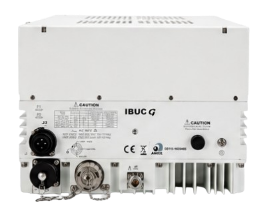
The IBUC G combines a number of characteristics that make it suitable for large-scale and demanding satellite networks.
These capabilities make the IBUC G more than simply a high-power amplifier. It is intended to function as an integrated RF subsystem within a professionally managed satellite network.
One of the most useful aspects of the IBUC G is its availability with different Ku-band frequency plans.
The manufacturer documentation identifies three frequency bands.
| Band | RF Frequency | IF Frequency | Local Oscillator |
|---|---|---|---|
| Band 1 – Standard Ku-Band | 14.00–14.50 GHz | 950–1450 MHz | 13.050 GHz |
| Band 2 – Full Ku-Band | 13.75–14.50 GHz | 950–1700 MHz | 12.800 GHz |
| Band 3 – Low Ku-Band | 12.75–13.25 GHz | 950–1450 MHz | 11.800 GHz |
The frequency plan is particularly important when selecting a BUC because the required RF range must match the satellite network, antenna system, modem, and regulatory operating parameters.
The IBUC G therefore provides flexibility for different Ku-band deployment requirements rather than limiting the user to a single RF plan.
The IBUC G is offered in two principal output-power configurations:
150W
and
200W
The difference is significant for network planners because available RF power directly affects the link budget and the ability to support multiple carriers.
The documentation specifies:
| Parameter | 150W Version | 200W Version |
|---|---|---|
| Rated Output Power | 150W | 200W |
| Psat, typical | 51.8 dBm | 53.0 dBm |
| PLin, minimum | 48.8 dBm | 50.0 dBm |
| PLin equivalent | 75W | 100W |
| 19 dB NPR point | 45.8 dBm | 47.0 dBm |
The manufacturer defines PLin as the maximum linear power according to MIL-STD 188-164C. The supplied documentation also states that the two-tone measurement is performed with carriers spaced at 5 MHz and 150 MHz.
This distinction between saturated power and linear operating power is especially important in multicarrier systems.

Satellite networks often transmit more than one carrier through the same RF chain. This creates a more demanding operating condition than a single-carrier application.
When several carriers are amplified simultaneously, nonlinear behavior can create intermodulation products and spectral distortion. For this reason, a BUC used in a multicarrier environment must be evaluated based not only on maximum output power but also on its linear operating characteristics.
The IBUC G documentation provides a 19 dB minimum Noise Power Ratio (NPR) specification at defined operating levels. The PLin values are associated with the maximum linear power definition from MIL-STD 188-164C.
For network designers, this makes the IBUC G particularly relevant where maintaining linearity across multiple carriers is important.
The IBUC G provides substantial gain between the L-band input and Ku-band RF output.
At an attenuator setting of 0 dB, the documentation specifies:
| Power Version | Standard Version Gain | WGS Version Gain |
|---|---|---|
| 150W | 83 dB minimum | 72 dB minimum |
| 200W | 83 dB minimum | 73 dB minimum |
The difference between the Standard and WGS-compatible versions is intentional.
According to the supplied documentation, the Terrasat Standard Version provides higher gain to reduce the need for line amplifiers in long IFL cable runs.
The WGS-compatible version has lower gain, allowing the IF signal to be driven up to 0 dBm.
This gives system integrators an important configuration choice depending on their IF distribution architecture.
The IBUC G includes a 30 dB variable attenuator, adjustable in 0.1 dB steps.
This is useful during system commissioning and optimization.
Instead of requiring external attenuation components for every power adjustment, the operator can configure the BUC’s attenuation to achieve the desired RF output level.
Fine 0.1 dB adjustment steps also provide precise control when optimizing the system’s operating point.
RF performance must remain predictable across the operating bandwidth and environmental conditions.
The IBUC G specifies:
| Parameter | Specification |
|---|---|
| Full-band gain flatness | 4 dB p-p maximum |
| 36 MHz gain flatness | 1.5 dB p-p maximum |
| 1 MHz gain flatness | 0.25 dB p-p |
| Open-loop gain variation over temperature | 4 dB p-p maximum |
| Gain variation with AGC | 1 dB p-p maximum |
These characteristics help demonstrate the product’s focus on controlled RF performance rather than simply maximum power output.
The AGC specification is particularly relevant because it helps maintain a more consistent output level as operating conditions change.
The IBUC G specifies ±0.5 dB level stability with ALC.
Automatic Level Control can be particularly valuable in professional satellite systems because maintaining a stable transmit level helps operators keep the RF chain operating within the intended configuration.
The output-power detector supports measurements from the rated power down to -20 dB, while the specified power-reading accuracy is ±1.0 dB maximum.
This provides operators with useful information for monitoring the RF output condition.
The IBUC G is also designed with defined unwanted-emission limits.
At PLin, the supplied documentation specifies:
The documentation also specifies output noise power density of:
These parameters are important when integrating a high-power amplifier into a satellite network where spectral cleanliness and interference management are essential.
Frequency stability is another critical characteristic in professional satellite transmission.
The IBUC G supports an external reference multiplexed on the TX IFL.
The external reference specification is:
Frequency: 10 MHz
Level: -12 to +5 dBm
The documentation also states that the internal-reference option includes automatic detection of the external reference.
The supplied phase-noise table is:
| Offset | IBUC G | External Reference |
|---|---|---|
| 10 Hz | -115 dBc/Hz | -50 dBc/Hz |
| 100 Hz | -140 dBc/Hz | -75 dBc/Hz |
| 1 kHz | -150 dBc/Hz | -85 dBc/Hz |
| 10 kHz | -155 dBc/Hz | -90 dBc/Hz |
| 100 kHz | N/A | -95 dBc/Hz |
| 1 MHz | N/A | -110 dBc/Hz |
The availability of an external 10 MHz reference is particularly useful in networks where frequency synchronization must be coordinated across multiple pieces of RF equipment.
The IBUC G uses a:
WR75 cover with groove
for its RF output interface.
The specified RF output VSWR is:
1.3:1 maximum.
On the IF side, the standard input is:
N Female, 50 Ohm
with optional:
The specified input VSWR and impedance are:
1.5:1 / 50 Ohm.
These interface options allow the IBUC G to be integrated into different IF distribution architectures.
The IBUC G also provides input power detection options.
The documentation specifies two ranges depending on the version:
| Version | Input Power Detector Range |
|---|---|
| Standard Version | -55 to -20 dBm |
| WGS Version | -35 to 0 dBm |
This corresponds with the different gain philosophies of the Standard and WGS-compatible configurations.
One of the strongest features of the IBUC G is its network management capability.
For Standard Versions, monitoring and control include:
This allows the BUC to be incorporated into a broader network-management system.
For large satellite networks, remote monitoring can significantly simplify operations because equipment status can be accessed without requiring technicians to physically reach the outdoor RF equipment.
The IBUC G is also available in cyber-hardened configurations.
The supplied documentation identifies the following features:
The manufacturer describes the cyber-hardened versions as incorporating enhanced cybersecurity features across both hardware and software, including a new controller board and firmware.
For critical infrastructure and managed satellite networks, this can be an important consideration when RF equipment is connected to operational management networks.
The IBUC G is designed for outdoor operation.
The specified environmental parameters are:
| Environmental Parameter | Specification |
|---|---|
| Operating Temperature | -40°C to +55°C |
| Relative Humidity | 100% condensing |
| Maximum Altitude | 10,000 ft / 3,000 m ASL |
These specifications allow the unit to be considered for demanding outdoor satellite installations where temperature and humidity can vary significantly.
The IBUC G uses AC power.
The supplied datasheet specifies:
200–240 VAC
at:
50/60 Hz
Power consumption is specified as:
| Operating Configuration | Power Consumption |
|---|---|
| 150W at PLin / PSat | 1150 VA / 1350 VA |
| 200W at PLin / PSat | 1150 VA / 1350 VA |
These figures should be incorporated into the site’s power and UPS planning during system design.
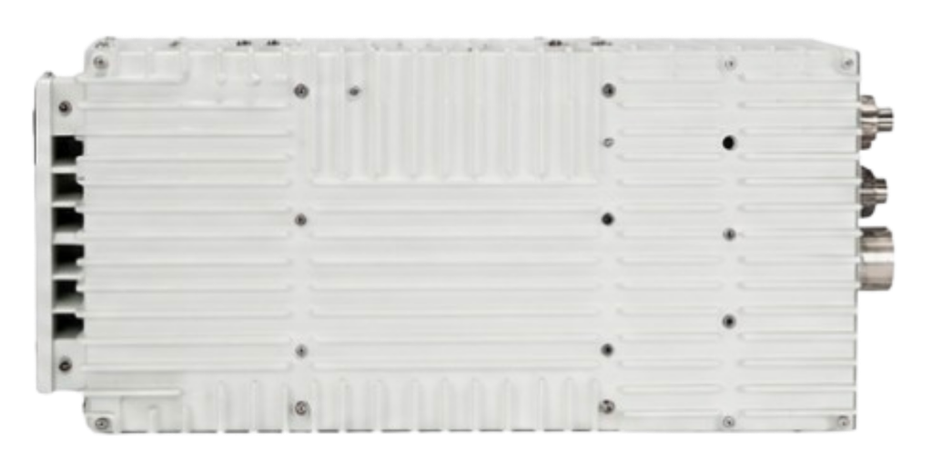
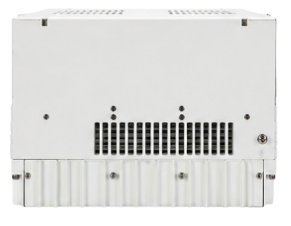
Despite its high RF output capability, the IBUC G remains a relatively compact outdoor RF unit for its power class.
The supplied documentation specifies:
Weight: 37 lb / 17 kg
Dimensions: 23 × 10 × 7.4 inches
or approximately:
584 × 254 × 188 mm
The dimensions exclude isolators.
The mechanical characteristics should be considered when designing the antenna installation, mounting arrangement, and outdoor equipment infrastructure.
The IBUC G’s combination of high output power, multicarrier capability, RF flexibility, monitoring, and environmental performance makes it suitable for several professional applications.
The 150W and 200W versions can provide substantial RF power for satellite terminals where higher EIRP is required.
This can be valuable for networks supporting high-capacity connectivity, especially when the link budget requires more transmit power.
The product is explicitly designed for multicarrier applications.
This makes it particularly relevant to networks where several carriers share the same RF amplification chain.
Large satellite hubs and teleport facilities can use high-power BUCs as part of their outbound RF infrastructure.
The monitoring and control capabilities also make the IBUC G suitable for centralized network operations.
Large enterprises operating remote sites can use high-power Ku-band transmission equipment where terrestrial connectivity is unavailable, unreliable, or insufficient.
The high RF output capability and multicarrier orientation can also make this class of equipment relevant to professional contribution and satellite distribution systems, subject to the specific network design and regulatory requirements.
The wide environmental operating range makes the IBUC G suitable for outdoor installations supporting infrastructure located in challenging environments.
The principal strengths of the Terrasat IBUC G can be summarized as follows.
With 150W and 200W configurations, the IBUC G provides substantial transmit power for demanding Ku-band applications.
The product is specifically documented for multicarrier operation and includes defined NPR and linear-power specifications.
Three frequency-plan options cover Standard Ku, Full Ku, and Low Ku requirements.
Up to 83 dB minimum gain is specified for the Standard 150W and 200W versions.
The integrated 30 dB attenuator provides adjustment in 0.1 dB steps.
Ethernet, SNMP, serial management, and FSK options support professional network operations.
Cyber-hardened configurations provide HTTPS, SSHv2, SNMPv3, FIPS 140-2 compatibility, and other security features.
The unit is specified for operation from -40°C to +55°C and up to 10,000 ft altitude.

| Category | Specification |
|---|---|
| Product | Terrasat IBUC G |
| Application | Multicarrier |
| Output Power | 150W / 200W |
| Band 1 RF | 14.00–14.50 GHz |
| Band 1 IF | 950–1450 MHz |
| Band 1 LO | 13.050 GHz |
| Band 2 RF | 13.75–14.50 GHz |
| Band 2 IF | 950–1700 MHz |
| Band 2 LO | 12.800 GHz |
| Band 3 RF | 12.75–13.25 GHz |
| Band 3 IF | 950–1450 MHz |
| Band 3 LO | 11.800 GHz |
| Input VSWR | 1.5:1 |
| Input Impedance | 50 Ohm |
| Standard Input Connector | N Female |
| Optional Input Connectors | Type F, TNC |
| Standard Gain, 150W | 83 dB min |
| Standard Gain, 200W | 83 dB min |
| WGS Gain, 150W | 72 dB min |
| WGS Gain, 200W | 73 dB min |
| Variable Attenuator | 30 dB |
| Attenuator Resolution | 0.1 dB |
| Full-Band Gain Flatness | 4 dB p-p max |
| 36 MHz Gain Flatness | 1.5 dB p-p max |
| 1 MHz Gain Flatness | 0.25 dB p-p |
| Temperature Gain Variation, Open Loop | 4 dB p-p max |
| Temperature Gain Variation, AGC | 1 dB p-p max |
| RF Interface | WR75 Cover with Groove |
| RF Output VSWR | 1.3:1 max |
| 150W Psat | 51.8 dBm typical |
| 200W Psat | 53.0 dBm typical |
| 150W PLin | 48.8 dBm min |
| 200W PLin | 50.0 dBm min |
| NPR | 19 dB min |
| ALC Level Stability | ±0.5 dB |
| Output Detector | Rated power to -20 dB |
| Power Reading Accuracy | ±1.0 dB max |
| In-Band Spurious | -65 dBc |
| Harmonics | -60 dBc max |
| TX Noise Density | < -73 dBm/Hz |
| RX Noise Density | < -145 dBm/Hz |
| External Reference | 10 MHz |
| External Reference Level | -12 to +5 dBm |
| AC Supply | 200–240 VAC |
| Frequency | 50/60 Hz |
| Operating Temperature | -40°C to +55°C |
| Humidity | 100% condensing |
| Altitude | 10,000 ft / 3,000 m ASL |
| Weight | 37 lb / 17 kg |
| Dimensions | 584 × 254 × 188 mm |
| Standard M&C | HTTP, Telnet, SNMPv2c |
| Cyber-Hardened M&C | HTTPS, SSHv2, SNMPv3 |
| Cyber Security | FIPS 140-2 compatible |
All specifications in the table above are based on the supplied Terrasat IBUC G 150W/200W documentation.
For organizations planning a high-power Ku-band satellite network, selecting the correct IBUC configuration is important. Customers should consider the required RF frequency plan, output power, IF architecture, gain requirements, connector configuration, reference configuration, and monitoring requirements before ordering.
VSATPlus offers the Terrasat IBUC G Ku-Band 150W / 200W for professional satellite communication applications.
Whether you are upgrading an existing VSAT network, deploying a new teleport, building a multicarrier hub, or requiring a high-power Ku-band RF subsystem, VSATPlus can assist with product selection and procurement.
When requesting a quotation, customers should provide the intended:
This information helps ensure that the correct IBUC configuration is selected for the intended satellite network.

The Terrasat IBUC G Ku-Band 150W / 200W is a high-power Intelligent Block Upconverter designed for professional multicarrier satellite communication applications.
Its combination of 150W or 200W RF output, up to 83 dB minimum gain, 30 dB adjustable attenuation, multiple Ku-band frequency plans, automatic level control, 10 MHz reference support, detailed RF monitoring, and advanced network-management capabilities makes it a powerful solution for demanding satellite networks.
The product’s environmental specifications further support outdoor deployment, with operation from -40°C to +55°C, 100% condensing humidity, and operation up to 10,000 ft / 3,000 m ASL.
For operators working with multiple carriers, the IBUC G’s linear operating specifications and minimum 19 dB NPR performance provide an important advantage when designing high-capacity RF systems.
The availability of Standard and WGS-compatible versions, multiple RF frequency plans, different IF connector options, internal or external frequency reference configurations, and standard or cyber-hardened monitoring also gives system integrators significant flexibility.
For organizations looking for a high-power Ku-band BUC for multicarrier satellite communication, the Terrasat IBUC G 150W/200W is a strong platform to consider.
The Terrasat IBUC G is available through VSATPlus. Contact VSATPlus today for pricing, availability, configuration assistance, and ordering information.