UAE: +971 6 55 222 55 | USA: +1 (833) VSAT 123

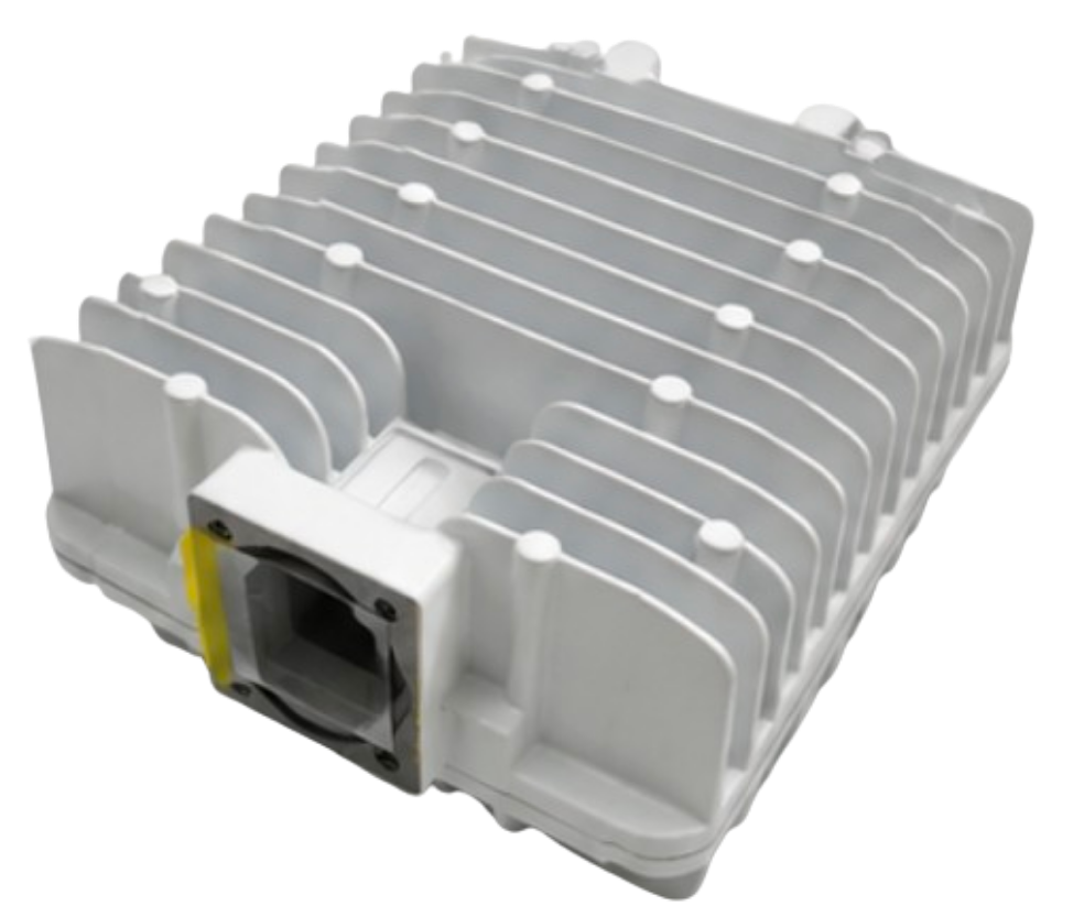
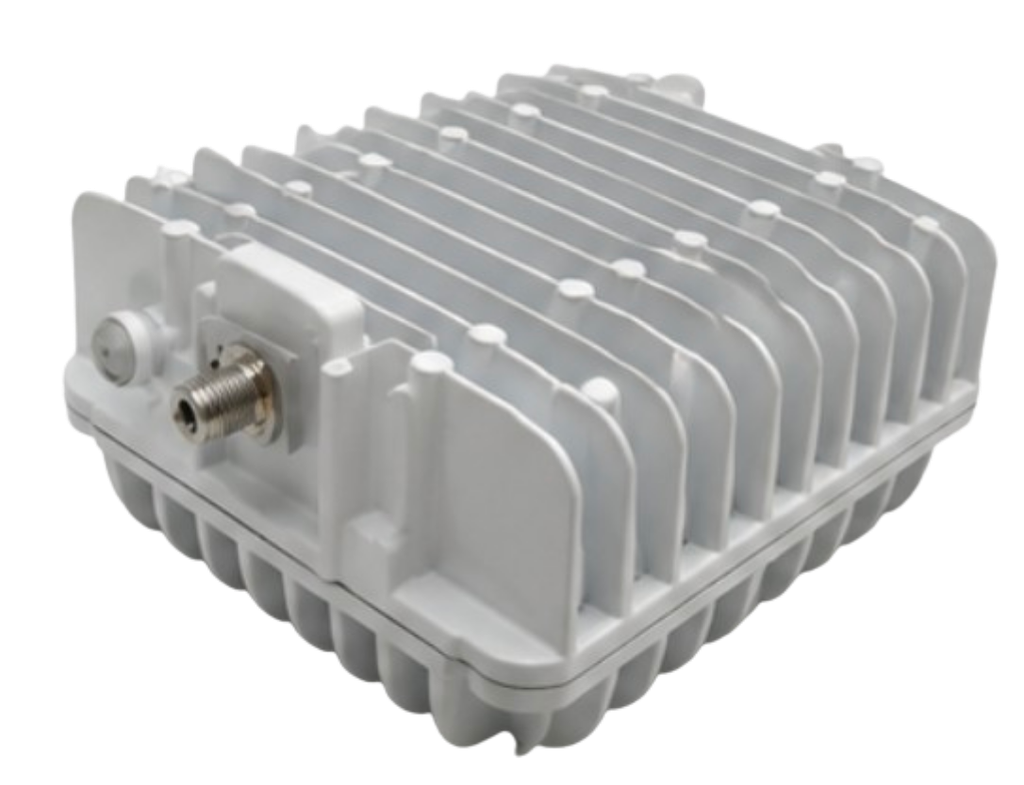
The USMonolithics / MTI / Viasat USBB35F20 3W Standard Ku-Band BUC is a compact, high-performance block upconverter designed for Ku-band satellite communication systems. With an RF output frequency range of 14.0–14.5 GHz, a minimum gain of 53 dB, a 35 dBm P1dB output compression point, and support for a 950–1450 MHz transmit IF input, the USBB35F20 provides a practical RF interface between a satellite modem and a Ku-band antenna feed system.
Its combination of high gain, compact mechanical dimensions, relatively low power consumption, external 10 MHz reference capability, and low phase-noise performance makes the unit suitable for a variety of professional VSAT and satellite communication applications.
The USBB35F20 is available through VSATPlus for customers looking for Ku-band BUC solutions for VSAT networks, remote connectivity, enterprise satellite communications, satellite infrastructure, and other RF applications.
A BUC (Block Upconverter) is one of the key RF components in a satellite transmit chain. Its primary function is to take a lower-frequency intermediate-frequency signal from a satellite modem and convert it to the much higher Ku-band frequency required for transmission toward the satellite.
In a typical VSAT transmit architecture, the signal path can be represented as:
Satellite Modem → IF Signal → BUC → Ku-Band RF → Antenna → Satellite
The USBB35F20 is designed to accept a transmit IF signal in the range of 950–1450 MHz and convert it to an RF output in the 14.0–14.5 GHz range.
The product uses a local oscillator frequency of 13.05 GHz, which enables the frequency conversion required for the Ku-band transmit range.
The unit is identified as a 3W Standard Ku-Band BUC, and its specified 1 dB gain compression point is at least 35 dBm, corresponding to approximately 3.16 W at the compression point. This provides the RF power level expected from a compact 3W-class Ku-band BUC.
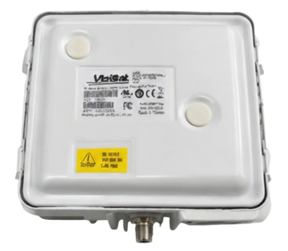
One of the most important characteristics of the USBB35F20 is its Ku-band transmit frequency range.
The specification sheet lists:
Output Frequency: 14.0–14.5 GHz
This places the BUC within the Ku-band satellite transmit spectrum commonly used for professional satellite communications.
The 500 MHz output range gives system integrators flexibility when configuring satellite terminals for different assigned frequencies within the supported range.
For satellite operators and VSAT installers, frequency compatibility is one of the first considerations when selecting a BUC. The USBB35F20 is therefore intended for systems where the required transmit carrier falls within its 14.0–14.5 GHz RF operating range.
The USBB35F20 is specified as a 3W Standard Ku-Band BUC.
The technical specification lists a:
1 dB Gain Compression Point (P1dB): ≥35 dBm
35 dBm corresponds to approximately 3.16 watts, which explains the product’s 3W-class designation.
The P1dB specification is particularly important in satellite transmission because it indicates the approximate output power level at which the amplifier begins to experience noticeable gain compression.
For practical satellite operation, the actual transmit power should be selected according to the satellite operator’s requirements, modem configuration, waveform, modulation, bandwidth, link budget, and any applicable linearity requirements.
The BUC should not simply be operated continuously at its compression point without considering the required output back-off for the specific application.
The USBB35F20 provides substantial amplification between its IF input and RF output.
The specification sheet lists:
Gain at Compression Point: 53 dB minimum
This high gain allows the BUC to accept the relatively low-power IF signal coming from a satellite modem and convert it into a substantially higher-power Ku-band RF signal.
The listed TX IF input power range is:
-10 to +7 dBm
This gives the system designer a defined input range for driving the BUC.
The exact required IF input level in a deployed system will depend on the desired RF output level and the BUC’s gain characteristics.
The USBB35F20 accepts a transmit intermediate-frequency signal from:
950–1450 MHz
This is particularly useful for satellite modems and VSAT equipment that provide their transmit output in the L-band IF range.
The IF input allows the BUC to be positioned directly after the satellite modem in a conventional VSAT transmit chain.
The architecture can therefore be summarized as:
950–1450 MHz IF → USBB35F20 → 14.0–14.5 GHz RF
This frequency conversion is the fundamental operation performed by the BUC.
The technical specification identifies the local oscillator frequency as:
13.05 GHz
The LO is fundamental to the upconversion process.
The BUC combines the incoming IF signal with the local oscillator to generate the required Ku-band output.
For example, conceptually:
13.05 GHz LO + 0.95 GHz IF = 14.00 GHz RF
and:
13.05 GHz LO + 1.45 GHz IF = 14.50 GHz RF
This explains how the specified 950–1450 MHz IF range maps onto the 14.0–14.5 GHz RF output range.

Phase noise is an important characteristic in satellite communication systems because excessive phase noise can degrade carrier quality and affect the performance of receivers and demodulators.
The supplied specification sheet provides the following single-sideband phase-noise specifications:
| Offset Frequency | Phase Noise |
|---|---|
| 100 Hz | < -60 dBc/Hz |
| 1 kHz | < -70 dBc/Hz |
| 10 kHz | < -80 dBc/Hz |
| 100 kHz | < -90 dBc/Hz |
These specifications describe the BUC’s phase-noise performance at different frequency offsets from the carrier.
Low phase noise is particularly valuable in satellite applications where carrier stability and spectral quality are important.
For professional VSAT deployments, maintaining clean RF performance can contribute to efficient spectrum utilization and predictable system performance.
The USBB35F20 supports an external 10 MHz reference through the IF interface.
The specification sheet states:
10 MHz REF received via IF Interface
with a reference input level of:
0 ± 5 dBm
The reference signal can be important in satellite communication systems where frequency synchronization between the modem and outdoor RF equipment is required.
Using a common reference can help maintain frequency alignment across the transmission chain.
This feature can be particularly useful in professionally engineered VSAT and satellite networks where precise frequency management is required.
The USBB35F20 uses:
RF Interface: WR-75
WR-75 is a standard waveguide interface used for Ku-band RF equipment.
The IF interface is specified as:
Type F (female) or N
This gives system integrators flexibility depending on the required physical and cabling configuration.
The specification sheet also lists:
IF Interface Impedance: 75 ohms
The impedance specification should be considered when selecting the appropriate coaxial cable, connectors, modem interface, and associated RF equipment.
The specification sheet lists the following VSWR characteristics:
RF VSWR: 2.0:1 maximum
IF VSWR: 2.0:1 maximum
VSWR, or Voltage Standing Wave Ratio, provides an indication of impedance matching between the BUC and the connected RF system.
Maintaining appropriate impedance matching is important because excessive mismatch can result in reflected power and reduced RF-system efficiency.
For satellite system designers, these values should be considered alongside the specifications of the antenna feed, waveguide components, coaxial cables, modem, and other equipment in the complete transmission chain.
The USBB35F20 is designed to operate from:
15–30 VDC nominal
The maximum specified power consumption is:
28 W
This makes the BUC suitable for installations where DC power is available at the outdoor equipment location.
Before installation, the system designer should verify that the satellite modem, power supply, or external DC source can provide the appropriate voltage and current required by the BUC.
Power-system compatibility is especially important in remote VSAT installations where equipment may be powered from batteries, solar systems, DC power supplies, or other limited power sources.
Outdoor satellite equipment may be exposed to substantial temperature variations.
The USBB35F20 is specified for an operating temperature range of:
-40°C to +50°C
Its storage temperature range is:
-55°C to +85°C
This wide temperature specification makes the BUC suitable for outdoor satellite communication equipment where environmental conditions can vary significantly.
For remote deployments, installers should still consider the complete environmental conditions of the installation, including direct solar exposure, enclosure design, ventilation, altitude, and surrounding equipment.
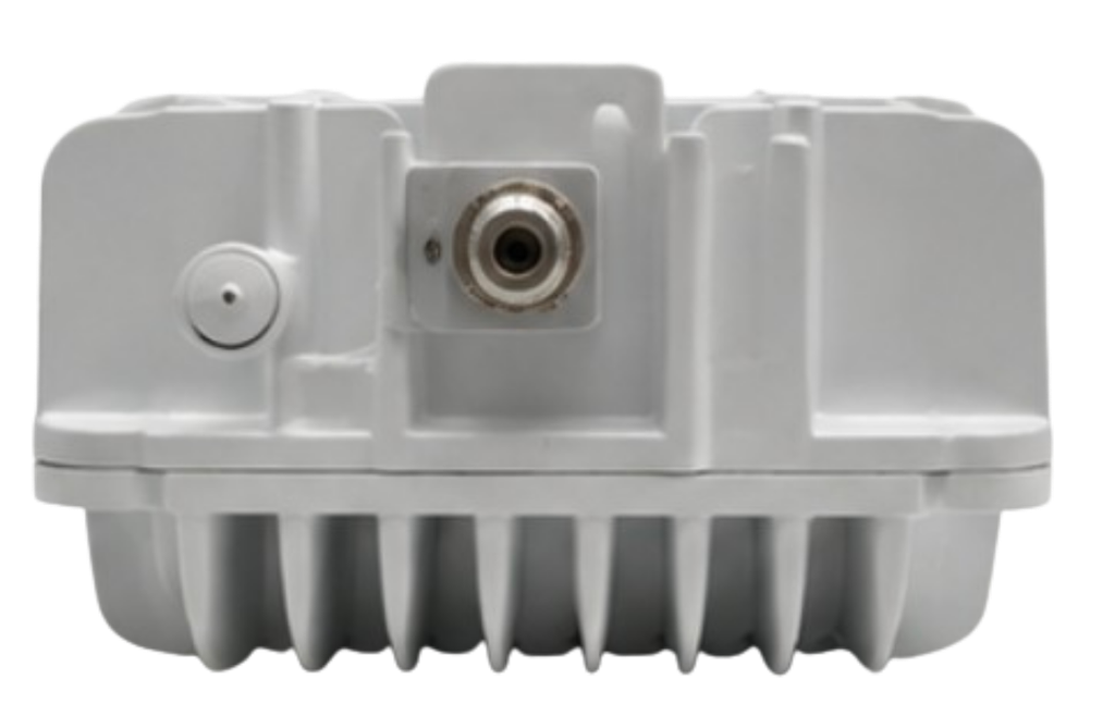
The following table summarizes the technical information shown in the supplied USBB35F20 specification document.
| Item | Specification |
|---|---|
| Product | USMonolithics / MTI / Viasat USBB35F20 |
| Product Type | 3W Standard Ku-Band BUC |
| Output Frequency | 14.0–14.5 GHz |
| 1 dB Gain Compression Point (P1dB) | ≥35 dBm |
| Gain at Compression Point | ≥53 dB |
| TX Intermediate Frequency | 950–1450 MHz |
| TX Input Power Level | -10 to +7 dBm |
| RF VSWR | 2.0:1 max. |
| IF VSWR | 2.0:1 max. |
| LO Frequency | 13.05 GHz |
| Phase Noise @ 100 Hz | < -60 dBc/Hz |
| Phase Noise @ 1 kHz | < -70 dBc/Hz |
| Phase Noise @ 10 kHz | < -80 dBc/Hz |
| Phase Noise @ 100 kHz | < -90 dBc/Hz |
| RF Interface | WR-75 |
| IF Interface Connector | Type F (female) or N |
| IF Interface Impedance | 75 ohms |
| 10 MHz Reference | Received via IF interface |
| 10 MHz Reference Level | 0 ± 5 dBm |
| Reference Phase Noise @ 100 Hz | < -135 dBc/Hz |
| Reference Phase Noise @ 1 kHz | < -140 dBc/Hz |
| Reference Phase Noise @ 10 kHz | < -143 dBc/Hz |
| DC Power | 15–30 VDC nominal |
| Maximum Power Consumption | 28 W |
| Operating Temperature | -40°C to +50°C |
| Storage Temperature | -55°C to +85°C |
| Dimensions | 166.45 × 121 × 56 mm |
| Weight | 1.1 kg |
Specifications in this table are based on the supplied USBB35F20 technical specification sheet.
In addition to the BUC’s own phase-noise specifications, the supplied documentation provides phase-noise information for the external reference.
The listed reference phase-noise values are:
| Reference Offset | Phase Noise |
|---|---|
| 100 Hz | < -135 dBc/Hz |
| 1 kHz | < -140 dBc/Hz |
| 10 kHz | < -143 dBc/Hz |
These specifications are relevant when the BUC is operated with an external 10 MHz reference.
The quality of the reference source can be important in systems where precise frequency stability and low phase noise are required. Consequently, system designers should consider not only the BUC but also the characteristics of the reference source being supplied to it.
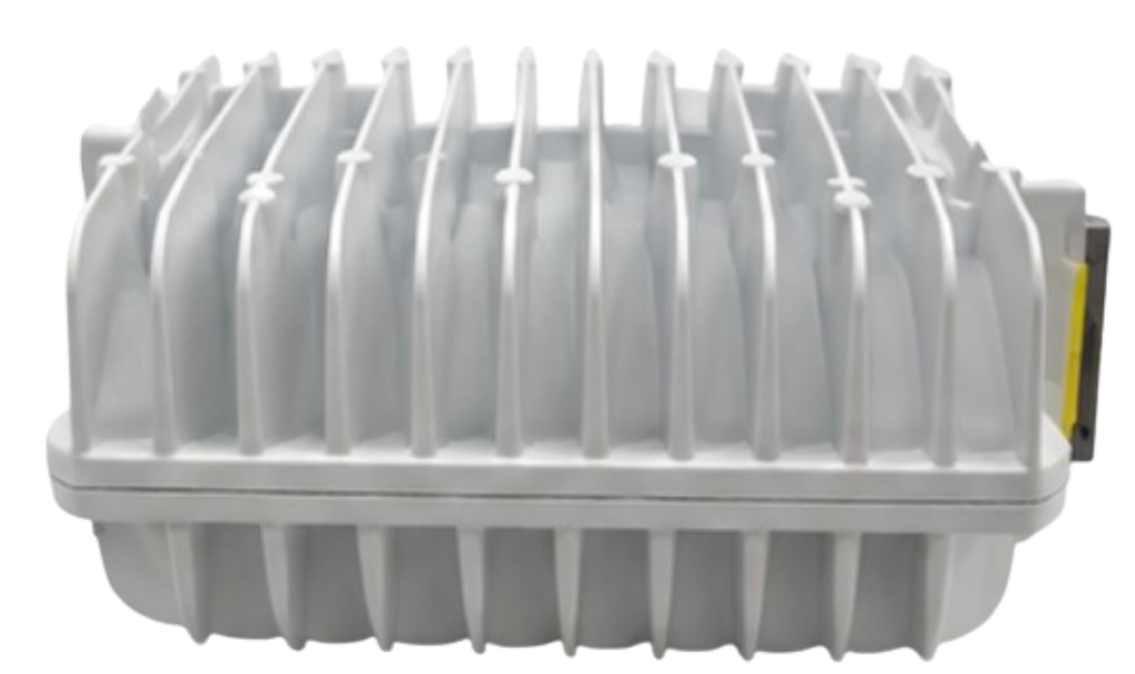
One of the primary applications for a 3W Ku-band BUC such as the USBB35F20 is VSAT.
In a conventional VSAT terminal, the modem generates the transmit IF signal. The BUC then converts this signal into Ku-band RF before it is delivered to the antenna feed.
The USBB35F20’s 950–1450 MHz IF input and 14.0–14.5 GHz RF output make it suitable for systems operating within those frequency ranges.
Enterprises operating remote offices, infrastructure, field locations, and facilities without dependable terrestrial connectivity can use Ku-band VSAT technology to establish satellite communications.
In these systems, the BUC is responsible for the uplink portion of the terminal.
A 3W-class BUC can be considered for applications where the link budget and satellite operator requirements are compatible with the available RF output power.
Satellite connectivity is frequently used in geographically remote locations.
Potential deployment environments can include:
The BUC’s -40°C to +50°C operating temperature range provides useful environmental capability for outdoor installations.
Another practical application is equipment replacement.
When maintaining an existing Ku-band VSAT network, system integrators may need to replace a failed or outdated BUC while maintaining compatibility with an existing modem and antenna system.
The USBB35F20 can be considered when its:
match the existing system.
This makes checking the complete technical configuration essential before ordering.

The unit provides 3W-class Ku-band RF output capability while maintaining a relatively compact form factor.
The 14.0–14.5 GHz output range covers a broad 500 MHz section of the Ku-band transmit spectrum.
With a minimum specified gain of 53 dB at the compression point, the unit provides substantial amplification between the IF input and RF output.
The supplied phase-noise specifications demonstrate progressively lower phase-noise levels at increasing offsets, reaching < -90 dBc/Hz at 100 kHz.
Support for an external 10 MHz reference provides additional frequency-reference flexibility for professionally engineered satellite networks.
Operation from -40°C to +50°C makes the unit appropriate for many outdoor satellite installations.
The combination of WR-75 RF interface and Type F female or N IF connector options supports integration into different system configurations.
The specification sheet lists a maximum power consumption of 28 W, an important consideration for remote and power-sensitive VSAT installations.
Although the USBB35F20 provides a strong technical package, selecting the correct BUC requires checking the complete satellite system.
Before ordering, customers should verify:
1. Satellite frequency:
The required transmit frequency must fall within 14.0–14.5 GHz.
2. Modem IF output:
The modem must provide an appropriate IF signal within 950–1450 MHz.
3. IF connector:
The installation should be compatible with the available Type F female or N interface configuration.
4. RF waveguide:
The antenna/feed assembly should support the specified WR-75 interface.
5. Power supply:
The system should provide the required 15–30 VDC nominal supply.
6. Link budget:
The 3W-class output capability should be evaluated against antenna size, satellite transponder characteristics, modulation, bandwidth, required EIRP, and satellite operator requirements.
7. Reference requirements:
If an external 10 MHz reference is required, the source should provide the appropriate 0 ±5 dBm reference level.
For satellite operators, system integrators, telecommunications companies, VSAT installers, and organizations deploying professional satellite connectivity, VSATPlus offers the USMonolithics / MTI / Viasat USBB35F20 3W Standard Ku-Band BUC.
The product can be considered for Ku-band VSAT terminals and other satellite communication systems requiring a compact 3W-class BUC with a 14.0–14.5 GHz RF output.
When requesting a quotation, customers should provide their intended satellite frequency, modem model, antenna/feed configuration, IF interface requirement, and power configuration. This information allows the required compatibility to be evaluated before procurement.
Contact VSATPlus for pricing, availability, and ordering information for the USBB35F20.

The USMonolithics / MTI / Viasat USBB35F20 3W Standard Ku-Band BUC F-Type is a compact RF upconverter designed for professional Ku-band satellite communication systems.
Its principal specifications include a 14.0–14.5 GHz RF output range, 950–1450 MHz transmit IF input, 13.05 GHz local oscillator, and a minimum 35 dBm P1dB output compression point. The unit also provides at least 53 dB gain at compression, with RF and IF VSWR specifications of 2.0:1 maximum.
The BUC supports an external 10 MHz reference, with the reference received through the IF interface, and provides low phase-noise performance at both the RF conversion and reference levels. Its WR-75 RF interface, Type F female or N IF connectivity, 75-ohm IF impedance, and 15–30 VDC nominal power requirement make it suitable for integration into a range of VSAT architectures.
From an environmental perspective, the -40°C to +50°C operating temperature range supports outdoor deployment, while the relatively compact 166.45 × 121 × 56 mm form factor and 1.1 kg weight simplify equipment integration.
For satellite operators and system integrators looking for a 3W-class Ku-band BUC, the USBB35F20 provides a combination of RF performance, frequency coverage, reference support, compact construction, and practical interfaces.
The USMonolithics / MTI / Viasat USBB35F20 is available through VSATPlus. Contact VSATPlus for pricing, availability, and ordering information.