UAE: +971 6 55 222 55 | USA: +1 (833) VSAT 123

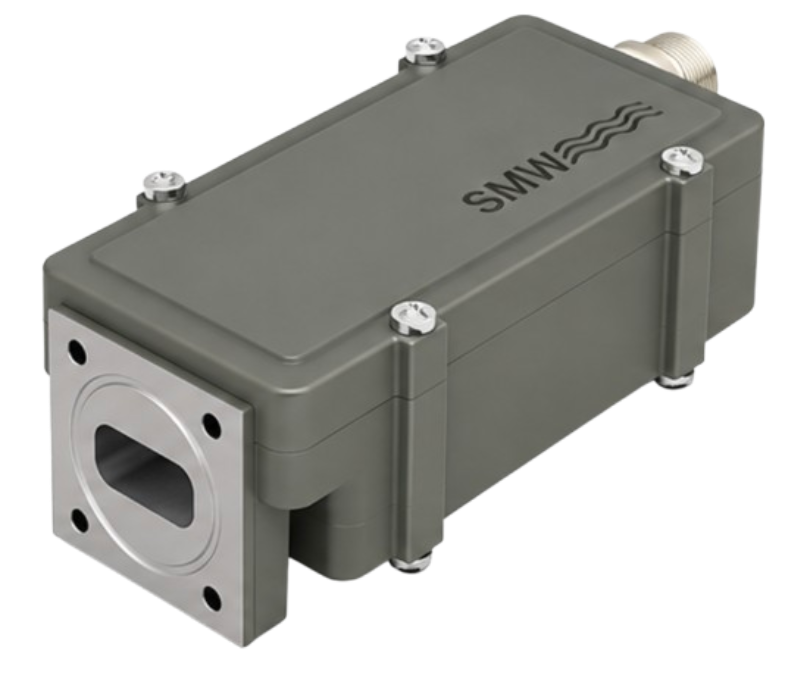
Reliable frequency conversion is a critical part of modern satellite communication systems. As satellite networks evolve to support higher data rates, wider bandwidths, and more demanding transmission requirements, professional ground-segment infrastructure must deliver excellent signal quality, frequency stability, and operational reliability.
The SMW Ka-Band Singleband BDC 17.30–22.30 GHz, manufactured by Swedish Microwave AB, is designed to meet these requirements. This high-performance Block Downconverter (BDC) is developed for satellite reception systems that require the conversion of a selected Ka-band frequency sub-band into an intermediate frequency (IF) suitable for further processing by satellite receivers, modems, and other downstream equipment.
The unit is particularly suitable for systems that use an existing Low Noise Amplifier (LNA) or require a separate BDC to work alongside an LNA. It supports multiple frequency configurations, offers adjustable gain, and provides automatic switching between internal and external frequency references.
With its excellent phase-noise performance, high output linearity, and wide operating temperature range, the SMW Ka-Band Singleband BDC is a practical solution for professional satellite communication installations.
VSATPlus provides access to professional satellite communication equipment, including SMW frequency conversion solutions. Customers can contact the VSATPlus team to request pricing, confirm availability, and identify the appropriate configuration for their system.
A Block Downconverter is an electronic device that converts a high-frequency RF signal into a lower intermediate frequency. This conversion allows satellite receivers and other ground-segment equipment to process signals that would otherwise be difficult to handle directly at their original RF frequencies.
In a Ka-band satellite reception system, the incoming signal is received at a frequency within the Ka-band spectrum. The BDC uses a Local Oscillator (LO) to translate the selected RF frequency range into an IF output.
The resulting IF signal can then be delivered to a satellite modem, receiver, or other processing equipment through a suitable coaxial connection.
The SMW Ka-Band Singleband BDC is designed to process one selected frequency sub-band within the broader 17.30–22.30 GHz range. It can be combined with an LNA or connected to an existing LNA-based reception system.
This architecture provides flexibility for satellite operators and system integrators who need to build or upgrade Ka-band reception infrastructure.
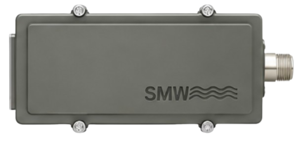
The BDC supports a selection of RF input frequency ranges and corresponding Local Oscillator configurations. Depending on the selected model, it can cover different one-gigahertz sub-bands across the Ka-band spectrum.
This flexibility allows system designers to select the configuration that matches their satellite frequency plan and receiver requirements.
The available standard LO configurations include 16.35, 16.75, 17.20, 17.25, 18.20, 18.25, 18.75, 19.20, 19.25, 20.20, and 20.25 GHz.
Customized LO configurations are also available as an option.
Frequency stability is essential in satellite reception systems. The SMW BDC supports both an internal frequency reference and an external 10 MHz reference.
The unit automatically switches between external and internal reference sources, helping maintain operation when the external reference becomes unavailable.
The internal reference provides a stability of ±2.5 ppm over the specified temperature range of -40°C to +80°C.
An external 10 MHz sine-wave reference can be supplied through the output connector, with an input level between -10 and +10 dBm.
The product offers strong output linearity through its specified P1dB and IP3 performance.
At gain settings of 30–40 dB, the minimum output P1dB is +5 dBm and the minimum output IP3 is +15 dBm.
At higher gain settings of 45–60 dB, these values increase to +15 dBm P1dB and +25 dBm IP3.
This performance helps the BDC handle demanding signal conditions while maintaining the quality of the converted IF output.
Phase noise is an important parameter in satellite communication systems because excessive phase noise can affect carrier quality and demodulation performance.
The SMW Ka-Band Singleband BDC provides low phase noise across a wide range of offset frequencies. Its specified performance supports demanding digital satellite transmission profiles, including DVB-S2X applications.
For the 19.20/19.25 GHz models, the integrated single-sideband phase noise over the 10 Hz to 16 kHz bandwidth is specified at less than 3.4° RMS.
The BDC offers typical gain settings from 30 dB to 60 dB, configurable in 5 dB steps.
Gain is factory programmable, allowing the unit to be configured for different system requirements.
The gain variation over 24 hours is specified at ±0.1 dB under the stated reference conditions of 23°C.
For installations requiring remote supervision, the BDC can be configured with optional alarm and Monitoring & Control functionality.
The optional interface uses MODBUS RTU over an RS485 electrical connection. Multiple units can be cascaded in an RS485 network, allowing centralized monitoring and control.
The optional alarm functionality can monitor selected conditions, including LNA failure, total current, LO lock status, signal power, and low supply voltage.
This is particularly useful in professional facilities where equipment status and fault detection are important for maintaining service availability.
The product is designed for operation in demanding environmental conditions.
Both its operating and storage temperature ranges are specified from -40°C to +80°C. This wide range makes it suitable for installations exposed to significant temperature variations.

The SMW Ka-Band Singleband BDC offers several practical advantages for satellite operators, teleport facilities, and system integrators.
Flexible system integration: Its compatibility with an LNA-based reception architecture makes it suitable for new installations as well as upgrades to existing Ka-band systems.
Multiple frequency options: A range of LO and RF configurations allows the product to support different satellite frequency plans.
Stable frequency conversion: Automatic reference switching and a specified internal reference stability of ±2.5 ppm help maintain reliable frequency conversion.
High linearity: Strong P1dB and IP3 specifications support signal handling across the available gain configurations.
Low phase noise: Its phase-noise performance is designed to support demanding digital satellite reception applications.
Configurable gain: Factory-programmable gain from 30 to 60 dB provides flexibility when integrating the BDC into different RF chains.
Remote monitoring options: Optional RS485/MODBUS RTU monitoring and alarm functionality can simplify equipment supervision.
Long-term reliability: The datasheet specifies high MTBF figures under the stated MIL-HDBK-217F calculation conditions.
The SMW Ka-Band Singleband BDC can be integrated into a variety of professional satellite communication systems.
Ground stations receiving Ka-band satellite signals require accurate frequency conversion before signals are delivered to downstream receivers. The BDC can form part of the RF reception chain, converting the selected Ka-band sub-band into an IF signal.
Teleports and satellite gateways often operate complex RF systems with multiple reception paths. The BDC’s configurable gain and frequency options make it suitable for integration into these installations.
Ka-band frequencies are widely used in high-capacity satellite broadband systems. The BDC can support the reception infrastructure by converting incoming RF signals into an intermediate frequency for further processing.
Satellite broadcast facilities require dependable signal reception and processing. The BDC can be used in Ka-band reception chains where the selected frequency range and IF output match the requirements of the receiving equipment.
The optional alarm and monitoring functionality can support installations where equipment status and RF-chain performance need to be supervised.
Its configurable frequency options, external reference support, and adjustable gain can also make the product suitable for specialized RF and satellite engineering environments.
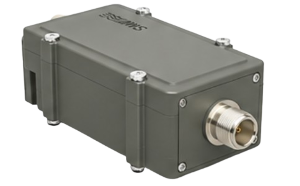
The following table summarizes the technical information provided in the manufacturer’s datasheet. Specifications are typical unless otherwise stated. The exact configuration should be confirmed against the required part number.
| Parameter | Specification |
|---|---|
| Product | SMW Ka-Band Singleband BDC |
| Overall frequency range | 17.30–22.30 GHz |
| Available LO configurations (GHz) | 16.35, 16.75, 17.20, 17.25, 18.20, 18.25, 18.75, 19.20, 19.25, 20.20, 20.25 |
| RF input configurations | 17.30–18.30, 17.70–18.70, 18.20–19.20, 19.20–20.20, 19.70–20.20, 20.20–21.20, 21.20–22.20 GHz, depending on model |
| Input connector | SMA female, 50 Ω |
| Input VSWR | 1.9:1 maximum, with included isolator |
| LO leakage at RF input | -60 dBm maximum |
| Parameter | Specification |
|---|---|
| IF output options | 950–1950 MHz, 1000–2000 MHz |
| Optional extended IF | 950–2250 MHz |
| Output connector options | N-type 50 Ω, SMA-type 50 Ω, or F-type 75 Ω |
| Output VSWR | 1.7:1 typical |
| LO leakage at IF output | -40 dBm maximum |
| Image rejection | 30 dB minimum |
| Group delay | ±1 ns maximum |
| Parameter | Specification |
|---|---|
| Gain | 30–60 dB typical |
| Gain adjustment | 5 dB steps |
| Gain configuration | Factory programmable |
| Gain variation over 24 hours | ±0.1 dB at 23°C |
| Gain flatness within 30 MHz | ±0.4 dB |
| Gain flatness over full band | ±2 dB maximum |
| Noise figure | 2–4 dB, depending on gain |
| Output P1dB at 30–40 dB gain | +5 dBm minimum |
| Output P1dB at 45–60 dB gain | +15 dBm minimum |
| Output IP3 at 30–40 dB gain | +15 dBm minimum |
| Output IP3 at 45–60 dB gain | +25 dBm minimum |
| Offset Frequency | Typical Phase Noise |
|---|---|
| 10 Hz | -35 dBc |
| 100 Hz | -65 dBc |
| 1 kHz | -80 dBc |
| 10 kHz | -85 dBc |
| 100 kHz | -95 dBc |
| Above 1 MHz | -112 dBc |
For the 19.20/19.25 GHz models, integrated single-sideband phase noise over 10 Hz to 16 kHz is specified at less than 3.4° RMS. The corresponding two-sided value is less than 4.8° RMS.
| Parameter | Specification |
|---|---|
| Reference system | Automatic switching between external and internal reference |
| Internal reference stability | ±2.5 ppm |
| Internal reference temperature range | -40°C to +80°C |
| External reference frequency | 10 MHz |
| External reference waveform | Sine wave |
| External reference input level | -10 to +10 dBm |
| DC input voltage | +12 to +26 VDC |
| DC input method | Through output connector or optional separate SMA connector |
| Maximum power consumption | 5 W |
| Parameter | Specification |
|---|---|
| Alarm functionality | Optional |
| Monitoring and Control | Optional |
| Communication interface | MODBUS RTU over RS485 |
| Alarm output | Open collector |
| Alarm voltage | 3.3–28 V |
| Maximum alarm current | 200 mA |
| Alarm conditions | LNA failure, total current, LO lock, signal power high/low, low supply voltage |
| Alarm connector | Pin 1 of optional M8 connector |
| M&C connector | Optional M8 female, 4-pin, A-coded |
| Cable requirement | Shielded cable |
| Parameter | Specification |
|---|---|
| Dimensions | 171 × 80 × 46 mm |
| Dimension configuration | N-connectors, including isolator |
| Weight | 418 g |
| Operating temperature | -40°C to +80°C |
| Storage temperature | -40°C to +80°C |
| MTBF – Ground Fixed (GF) | >690,000 hours |
| MTBF – Airborne, Inhabited, Cargo (AIC) | >360,000 hours |
| MTBF calculation standard | MIL-HDBK-217F, Notice 2 |
| Quality level | Commercial |
| Ambient temperature used for MTBF calculation | +35°C |
| Option | Description |
|---|---|
| Customized gain | Gain configuration tailored to the system |
| Customized LO | Custom Local Oscillator frequency |
| Extended IF | Optional IF output range of 950–2250 MHz |
| Extended input frequency | Input frequency configuration starting from 17.20 GHz |
| Separate SMA connector | Optional DC input or external 10 MHz reference connection |
| Alarm and M&C | Optional alarm and remote monitoring functionality |
| Connector alternatives | F female or SMA female input connector options |
Note: Technical specifications are based on the manufacturer’s Rev. 2501 datasheet. Specifications are typical and may vary by part number or configuration. Please confirm the exact model and options before ordering.

Selecting the correct BDC configuration is important for achieving the required performance in a satellite reception system.
Before ordering, system designers should confirm the incoming RF frequency range, required LO frequency, and IF output range. These parameters must match the satellite frequency plan and the capabilities of the connected receiver or modem.
The required output connector and impedance should also be considered. The product offers N-type and SMA-type 50 Ω options, as well as an F-type 75 Ω option.
Power requirements must be checked carefully. The BDC accepts +12 to +26 VDC, with power consumption of up to 5 W. Power can be supplied through the output connector or through an optional separate SMA connector.
For systems using an external 10 MHz reference, the reference signal must meet the specified waveform and input-level requirements.
If remote monitoring is required, the optional RS485/MODBUS RTU interface and alarm configuration should be included in the equipment selection process.
Because the available models have different RF and IF frequency combinations, customers should provide their system requirements when requesting a quotation.
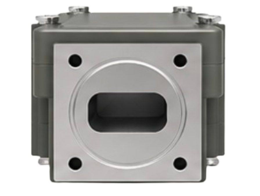
Choosing the right satellite communication component involves more than selecting a product with a suitable frequency range. Compatibility with existing equipment, system configuration, connector requirements, and long-term operational needs are equally important.
VSATPlus supplies professional satellite communication equipment and solutions for customers across commercial, enterprise, broadcast, maritime, and telecommunications markets.
Through VSATPlus, customers can request the SMW Ka-Band Singleband BDC 17.30–22.30 GHz and receive assistance in identifying the appropriate configuration for their application.
Whether you are developing a new Ka-band ground station, upgrading an existing satellite reception chain, or sourcing a frequency conversion component for a professional RF installation, the VSATPlus team can help you review the available options.
Contact VSATPlus to:
The SMW Ka-Band Singleband BDC 17.30–22.30 GHz is a flexible and high-performance frequency conversion solution for professional satellite reception systems. Its multiple frequency configurations, automatic reference switching, adjustable gain, strong output linearity, and low phase-noise performance make it a valuable component in modern Ka-band RF infrastructure.
With optional remote monitoring, alarm functionality, customized LO configurations, and extended IF options, the product can be adapted to a variety of system requirements.
For satellite operators, teleport facilities, broadcasters, and system integrators seeking dependable Ka-band frequency conversion, this SMW BDC offers a combination of performance, flexibility, and integration options.
Order the SMW Ka-Band Singleband BDC 17.30–22.30 GHz through VSATPlus.
Visit www.vsatplus.com or contact the VSATPlus sales team at sales@vsatplus.com for pricing, availability, and configuration assistance.