UAE: +971 6 55 222 55 | USA: +1 (833) VSAT 123


Reliable signal distribution is a fundamental requirement in modern satellite communication networks. Satellite operators, teleport facilities, broadcast service providers, and network infrastructure managers need dependable equipment to distribute and combine RF signals across multiple receivers, transmitters, and communication systems. As satellite networks become more complex and support wider frequency ranges, signal distribution equipment must deliver consistent performance, high linearity, and flexible configuration options.
The Quintech QS/QC Series Extended L-Band Splitters & Combiners is designed to address these requirements. Developed by Quintech Electronics & Communications, the QS/QC Series builds upon the established LS and LC product families, extending their signal distribution capabilities across a wide frequency range of 950–4000 MHz.
The series offers both passive and active configurations, multiple output arrangements, flexible LNB power options, and single or redundant power supply configurations. These capabilities make it suitable for professional satellite communication environments where signal quality, operational flexibility, and system reliability are essential.
For organizations looking to expand an existing satellite infrastructure or build a new signal distribution system, the QS/QC Series provides a configurable platform for managing extended L-band signals.
VSATplus offers satellite communication equipment and solutions for professional networks. Customers interested in the Quintech QS/QC Series can contact VSATPlus for product availability, configuration information, pricing, and ordering assistance.
The Quintech QS/QC Series is a family of RF signal distribution products designed to split or combine satellite intermediate-frequency signals across multiple output paths.
The product family supports an extended L-band operating range of 950–4000 MHz, allowing it to accommodate a broad range of satellite communication applications. Its 50-ohm RF architecture is intended for professional RF distribution systems that require compatibility with standard satellite and telecommunications infrastructure.
The series is available in different configurations, including 1×2, 1×4, 1×8, 1×16, and 1×32 arrangements. Depending on the selected configuration, users can distribute a single signal to multiple destinations or combine multiple signal paths within a centralized distribution system.
One of the important characteristics of this product family is its availability in both passive and active configurations. Passive splitters distribute an input signal without active amplification, while active configurations provide signal gain and are suitable for applications requiring different signal-level characteristics.
The series also provides adjustable LNB power options, including 13V/18V switching with a 22 kHz tone and fixed 24V options. This flexibility helps integrators accommodate different LNB requirements and satellite system designs.

The QS/QC Series supports an operating frequency range of 950–4000 MHz.
This extended range provides flexibility for satellite communication installations that operate beyond conventional L-band requirements. It allows system integrators to design distribution architectures that accommodate a wider range of RF signals and equipment.
Benefits:
The product family is available in passive and active configurations.
Passive configurations are useful when signal distribution is required without active amplification. Active configurations provide an alternative for systems that require a different gain and signal-level arrangement.
This choice allows engineers to select a configuration based on signal budgets, network architecture, and the requirements of connected equipment.
Benefits:
The QS/QC Series is available in several distribution arrangements:
These options allow the equipment to support installations ranging from relatively small signal distribution systems to larger centralized facilities.
For example, a 1×4 configuration can distribute an input signal across four paths, while a 1×16 or 1×32 configuration can support a larger number of destinations.
Benefits:
LNB power management is an important consideration in satellite RF distribution systems.
The QS/QC Series supports several LNB power arrangements, including:
These options allow system designers to select a suitable power arrangement based on the connected LNB and the overall installation.
The datasheet also identifies DC-powered options where the switched LNB voltage matches the input supply.
The QS/QC Series supports single and redundant AC or DC power supply arrangements.
Redundant power options are particularly valuable in professional satellite facilities where maintaining service availability is important. A redundant power architecture can help reduce the risk of service interruption caused by a single power supply failure.
The product also includes power supply status monitoring, allowing operators to monitor the condition of the power system.
Benefits:
The QS/QC Series is designed for installation in a standard 19-inch equipment rack.
Its enclosure occupies 1RU of rack space, with dimensions of:
1.75 inches high × 19 inches wide × 7 inches deep.
This compact design helps integrate signal distribution equipment into professional satellite racks, teleport facilities, broadcast control rooms, and telecommunications infrastructure.

Signal distribution equipment must maintain predictable RF performance across its operating frequency range. Insertion loss, return loss, isolation, noise figure, and linearity are important parameters when designing a reliable RF distribution network.
The QS/QC Series provides specifications for these performance characteristics.
Insertion loss describes the reduction in signal power as a signal passes through a distribution device.
For passive splitter configurations, the datasheet provides different insertion-loss values depending on the number of outputs and the operating frequency range.
For active configurations, the datasheet provides insertion-loss/gain figures around 0 dB, with specified tolerances.
These values are important when engineers calculate the signal budget of a satellite distribution network.
The datasheet specifies an input 1 dB compression point of:
0 dBm per input.
The 1 dB compression point indicates the input level at which the device begins to exhibit significant gain compression. This parameter is important when determining the maximum operating signal level and avoiding nonlinear performance.
Noise figure describes the additional noise introduced by a device.
The QS/QC Series specifies different maximum noise figures for splitter and combiner operation, depending on the operating frequency range.
Lower noise contribution is important in RF distribution systems because excessive noise can reduce the quality of signals delivered to downstream equipment.
Isolation describes how effectively signal paths are separated from one another.
Port-to-port isolation and isolation between dividers are important when multiple receivers or signal paths share the same distribution infrastructure. Adequate isolation helps limit unwanted interaction between connected paths.
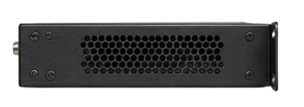
The Quintech QS/QC Series can be used in several professional satellite communication and RF distribution environments.
Teleport facilities manage large numbers of satellite signals and frequently require centralized RF distribution.
The QS/QC Series can be incorporated into signal distribution architectures where L-band signals must be routed to multiple receivers, modems, monitoring systems, or other RF equipment.
Its multiple output configurations make it suitable for different system sizes.
Satellite ground stations require reliable RF infrastructure to support communication between antennas, receivers, modems, and network equipment.
The QS/QC Series can help distribute intermediate-frequency signals within a ground station, depending on the station’s RF architecture and signal requirements.
Broadcast facilities often distribute satellite signals to multiple processing, monitoring, and receiving systems.
The QS/QC Series provides configurable distribution options for installations that need to deliver satellite IF signals to multiple destinations.
VSAT networks use satellite terminals and centralized hubs to provide connectivity to remote locations.
Within suitable hub or gateway architectures, L-band splitters and combiners can support the distribution and combination of RF signal paths.
The QS/QC Series offers different port configurations to accommodate varying network requirements.
Telecommunications facilities may use satellite connectivity as part of their backhaul, remote-site connectivity, or backup communication infrastructure.
The QS/QC Series can form part of the RF distribution layer where extended L-band signal handling is required.
Professional RF installations frequently require signals to be delivered to both operational equipment and monitoring instruments.
Depending on the selected configuration, the QS/QC Series can support signal distribution to multiple destinations, helping engineers organize RF connections within a centralized rack.
The following table summarizes the technical information provided in the Quintech QS/QC Series datasheet.
| Parameter | Specification |
|---|---|
| Product Series | Quintech QS/QC Series |
| Product Type | Extended L-Band Splitters & Combiners |
| Operating Frequency | 950–4000 MHz |
| Impedance | 50 Ω |
| RF Connectors | SMA Female |
| Available Configurations | 1×2, 1×4, 1×8, 1×16, 1×32 |
| 1×2 Options | Single, Dual, Quad |
| 1×4 Options | Single, Dual, Quad |
| 1×8 Options | Single, Dual |
| 1×16 Options | Single, Dual |
| 1×32 Options | Single |
| Operating Modes | Passive and Active |
| Input P1dB | 0 dBm per input |
| AC Input Range | 100–240 VAC, autoranging, 50/60 Hz, 5 A |
| DC Input Range | 12–24 VDC or optional −48 VDC |
| LNB Power | Switched 13V/18V, 22 kHz tone, up to 750 mA |
| Alternative LNB Power | Switched 24V at 500 mA for specified AC option |
| Maximum Input Power (No Damage) | 20 dBm |
| Maximum DC Voltage on Any Port | 30 VDC |
| Typical Power Consumption | 10 W, plus customer LNB power load |
| Power Options | Single or redundant AC/DC |
| Power Monitoring | Power supply status monitoring |
| Rack Size | 1RU |
| Dimensions | 1.75 × 19 × 7 inches |
| Net Weight | 3 lbs |
| Gross Weight | 6 lbs, boxed |
| Parameter | 1×4 | 1×8 | 1×16 |
|---|---|---|---|
| Passive Splitter Insertion Loss, 950–4000 MHz | −8 ± 2.0 dB | −11 ± 3.0 dB | −15 ± 3.0 dB |
| Passive Splitter Insertion Loss, 950–2450 MHz | −8 ± 1.5 dB | −11 ± 2.0 dB | −15 ± 2.0 dB |
| Active Combiner Insertion Loss/Gain, 950–4000 MHz | 0 ± 1.5 dB | 0 ± 2.0 dB | 0 ± 2.0 dB |
| Active Combiner Insertion Loss/Gain, 950–2450 MHz | 0 ± 1.0 dB | 0 ± 1.0 dB | 0 ± 1.0 dB |
| Parameter | Datasheet Specification |
|---|---|
| Input P1dB | 0 dBm per input |
| Noise Figure, 950–4000 MHz | Splitter: 10 dB max; Combiner: 23 dB max |
| Noise Figure, 950–2450 MHz | Splitter: 8 dB max; Combiner: 20 dB max |
| OIP3 | 10 dBm minimum |
| Input Return Loss | 12 dB (950–4000 MHz); 14 dB (950–2450 MHz) |
| Output Return Loss | 14 dB |
| Port-to-Port Isolation, Same Divider | 18 dB / 14 dB as listed for the applicable configurations |
| Isolation Between Dividers | 50 dB |
Specification note: The datasheet presents some RF performance values in a compact table, and individual performance may vary with connector type and configuration. The return-loss and isolation figures above are expressed in dB, consistent with the nature of those RF parameters; the exact values for a particular model should be confirmed against its individual specification sheet. The datasheet also identifies optional features with an asterisk.
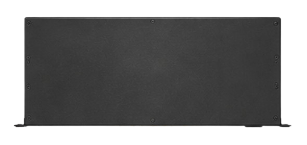
The QS/QC Series offers several practical advantages for satellite communication system designers and operators.
Wide Frequency Coverage: Its 950–4000 MHz operating range supports extended L-band applications and gives system integrators greater frequency flexibility.
Multiple Distribution Configurations: The availability of 1×2 through 1×32 arrangements allows users to select a suitable configuration for different network sizes.
Passive and Active Options: Having both passive and active configurations provides additional flexibility when designing RF signal paths.
Flexible LNB Power Management: Support for 13V/18V switching, 22 kHz tone control, and fixed 24V options helps accommodate different LNB power requirements.
Redundant Power Options: Optional redundant AC or DC power arrangements support installations where power resilience is important.
Power Supply Monitoring: Power supply status monitoring helps operators oversee the condition of the equipment’s power system.
Rack Integration: The 1RU enclosure is designed for standard 19-inch racks, making integration into existing facilities more straightforward.
Scalable Infrastructure: Different output configurations allow the signal distribution architecture to be selected according to the number of connected devices and the requirements of the installation.

Selecting the correct QS/QC Series configuration requires an understanding of the wider RF system.
Before ordering, system integrators should consider the following points:
A complete system review before ordering helps ensure that the selected unit is appropriate for the intended application.
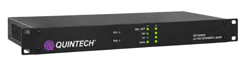
Choosing the right RF distribution equipment is an important part of building a dependable satellite communication system. In addition to selecting the correct product, buyers need to ensure that the configuration matches their technical requirements.
VSATplus provides access to satellite communication products and professional equipment for customers operating in the satellite, telecommunications, broadcast, maritime, and related industries.
Customers interested in the Quintech QS/QC Series Extended L-Band Splitters & Combiners can contact VSATPlus to:
Whether you are upgrading a teleport facility, expanding a satellite ground station, or developing an RF distribution network, VSATPlus can help you source the equipment required for your project.
The Quintech QS/QC Series Extended L-Band Splitters & Combiners provides a flexible approach to professional satellite signal distribution. With an operating range of 950–4000 MHz, multiple output configurations, passive and active options, flexible LNB power arrangements, and optional redundant power supplies, the series is designed to support a wide variety of RF distribution requirements.
Its compact 1RU rack-mount design makes it suitable for integration into professional satellite facilities, while its range of configurations allows system designers to select an arrangement that matches their installation.
For satellite operators, broadcast facilities, teleport engineers, and system integrators seeking extended L-band signal distribution equipment, the QS/QC Series is a product family worth considering.
Order the Quintech QS/QC Series Extended L-Band Splitters & Combiners from VSATPlus.
Contact our team for pricing, availability, and assistance in selecting the right configuration for your satellite communication infrastructure.
VSATPlus – Your Trusted Source for Satellite Communication Equipment
Website: www.vsatplus.com
Email: sales@vsatplus.com