UAE: +971 6 55 222 55 | USA: +1 (833) VSAT 123

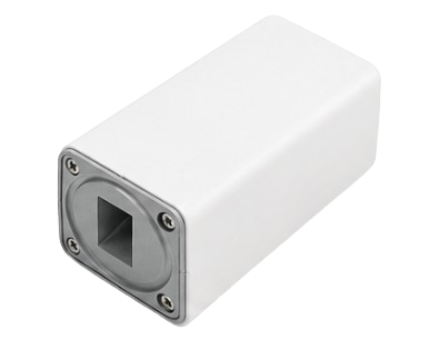
Reliable RF performance is one of the most important requirements in any professional satellite communication system. At the antenna feed, the Low Noise Block downconverter (LNB) plays a critical role by receiving the high-frequency Ku-band signal from the satellite, amplifying it while maintaining a low noise contribution, and converting it to an intermediate frequency that can be transmitted through coaxial cable to the satellite modem.
The New Japan Radio (NJR) Universal Ku-band 2LO PLL LNB series, including the NJR2841L, NJR2842L, and NJR2843L, is designed for this purpose. The series combines full Ku-band coverage, two selectable local oscillator frequencies, PLL-based frequency generation, an integrated reference architecture, compact mechanical construction, and multiple methods for selecting the required local oscillator.
According to the supplied NJR datasheet, the series covers the complete Ku-band range from 10.70 to 12.75 GHz, with low-band and high-band operation using 9.75 GHz and 10.6 GHz local oscillator frequencies respectively.
For satellite operators, VSAT installers, system integrators, telecommunications companies, and network operators, this architecture provides flexibility when deploying Ku-band satellite terminals.
VSATPlus offers satellite communication and RF equipment for professional applications and can assist customers looking to source the NJR Universal Ku-band 2LO PLL LNB series.
An LNB, or Low Noise Block downconverter, is installed at the receiving side of a satellite antenna system. Satellite signals arrive at the antenna at very high RF frequencies. These frequencies are generally too high to be transported directly through conventional coaxial cable to a satellite modem.
The LNB therefore performs three primary functions:
The NJR2841L/42L/43L family is specifically designed as a Universal Ku-band 2LO PLL LNB with switchable local oscillator frequencies.
The two local oscillator frequencies are:
The corresponding RF input ranges are:
This gives the series complete specified Ku-band coverage from 10.70 to 12.75 GHz.
The resulting IF ranges are:
This allows the converted signal to be delivered to the satellite modem through the LNB’s IF output connection.
One of the strongest features of the NJR series is its ability to cover the full specified Ku-band satellite downlink spectrum.
Instead of requiring different LNB hardware for separate portions of the Ku-band, the Universal design uses two selectable local oscillator frequencies.
| Band | RF Input Frequency | Local Oscillator | IF Output |
|---|---|---|---|
| Low Band | 10.70–11.70 GHz | 9.75 GHz | 950–1,950 MHz |
| High Band | 11.70–12.75 GHz | 10.60 GHz | 1,100–2,150 MHz |
| Total Coverage | 10.70–12.75 GHz | 9.75 / 10.6 GHz | 950–2,150 MHz* |
*The IF ranges are band-dependent and overlap between 1,100 and 1,950 MHz.
This flexibility is particularly useful for satellite installations where different transponders or satellite services operate across different portions of the Ku-band.
The NJR series is built around a two-LO architecture.
The LNB can select between:
9.75 GHz for low-band operation and 10.6 GHz for high-band operation.
The datasheet provides three different approaches for selecting the local oscillator.
The NJR2841L series uses a mechanical switch to select the local oscillator frequency.
This provides a straightforward approach for installations where the required local oscillator can be manually selected.
The NJR2842L series uses a 22 kHz tone On/Off control method.
This approach allows the connected equipment to select the required local oscillator electronically rather than requiring physical access to the outdoor LNB.
For installations where remote or automated band selection is desirable, this configuration can provide a practical advantage.
The NJR2843L series selects the local oscillator according to the input voltage condition, using high/low voltage selection.
This provides another option for system designers depending on the architecture of the satellite terminal and modem.
The family therefore gives integrators flexibility in selecting the control method most appropriate for their equipment.
The NJR2841L/42L/43L series uses PLL technology for its local oscillator architecture.
Frequency stability is an important factor in satellite communications because the local oscillator determines the frequency conversion performed inside the LNB.
The supplied datasheet specifies a local stability of:
±50 ppm
The integrated reference architecture is identified in the datasheet as Internal Reference ±50 ppm.
For satellite reception systems, stable frequency conversion helps maintain predictable IF performance and supports reliable integration between the LNB and the satellite modem.
The datasheet also provides phase-noise specifications for the local oscillator.
| Offset Frequency | Phase Noise |
|---|---|
| 100 Hz | -50 dBc/Hz typ. |
| 1 kHz | -70 dBc/Hz typ. |
| 10 kHz | -75 dBc/Hz typ. |
| 100 kHz | -85 dBc/Hz typ. |
The datasheet notes that the phase-noise performance can depend on the phase noise of the external reference where applicable.
The noise figure of an LNB is an important parameter because the LNB is located at the beginning of the satellite receive chain.
The NJR series specifies:
0.8 dB typical noise figure at +25°C
with a maximum specified value of:
1.0 dB
A low noise figure is desirable because the received satellite signal can be relatively weak. Minimizing noise added by the receiving equipment helps preserve the quality of the RF signal before it reaches the satellite modem.
For professional Ku-band VSAT systems, this makes the NJR series suitable for applications where RF receive performance is an important part of the overall link budget.

The NJR Universal Ku-band PLL LNB provides significant conversion gain.
The supplied documentation specifies:
48 dB minimum
and
62 dB maximum
at an ambient temperature of +25°C.
Conversion gain represents the amplification provided while the LNB converts the incoming Ku-band RF signal into its lower IF frequency.
The appropriate gain requirement ultimately depends on the complete RF system, including:
Therefore, the LNB should always be evaluated as part of the complete satellite RF chain rather than as an isolated component.
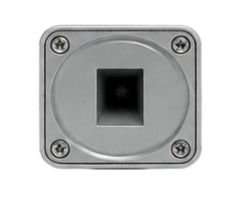
The NJR series uses a WR75 waveguide interface with groove at the RF input.
WR75 is a commonly used waveguide size for Ku-band antenna/feed assemblies.
The datasheet specifies:
RF Input Interface: WR75 waveguide with groove
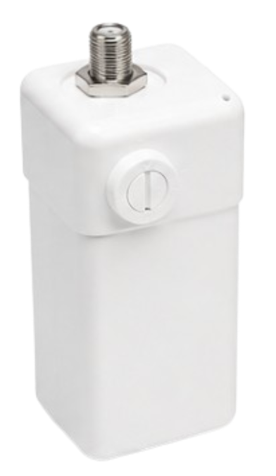
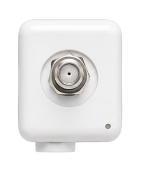
At the IF side, customers can choose between F-type and N-type configurations depending on the model.
The F-type models use:
F-type female, 75-ohm connector
These include:
The N-type models use:
N-type female, 50-ohm connector
These include:
The IF connector also carries the DC power required by the LNB.
The datasheet identifies the connection as:
IF/DC Power: +10 to +24 VDC
This integrated power-and-IF architecture simplifies the outdoor RF connection by allowing DC supply and the converted satellite signal to share the same interface.
The NJR series is designed for relatively straightforward DC powering.
The datasheet specifies:
Power Requirement: +24 VDC (+10 to +24 VDC)
and:
Current Drain: 200 mA maximum
This means system designers should ensure that the connected modem, power inserter, or other equipment is capable of supplying the required voltage and current.
Before installation, it is recommended to verify compatibility between the selected NJR LNB configuration and the connected satellite modem or RF equipment.
Physical size and weight are important considerations for antenna-mounted equipment.
The NJR series has a compact rectangular housing designed for integration with satellite antenna feed assemblies.
For the F-type configurations, the datasheet specifies:
NJR2841L:
83.4 × 42 × 42 mm
For the smaller housing used by:
NJR2842L / NJR2843L:
82.2 × 40 × 40 mm
The weight is:
210 g for F-type models
and:
240 g for N-type models.
The lightweight construction is beneficial for antenna installations because the LNB contributes relatively little additional mechanical load to the feed assembly.
Satellite equipment is often installed outdoors and may be exposed to substantial temperature changes.
The NJR series is specified for:
Operating temperature: -40°C to +60°C
and:
Storage temperature: -40°C to +80°C
This wide temperature range allows the LNB to be considered for outdoor satellite installations operating in demanding environmental conditions.
The environmental specifications are particularly relevant to VSAT terminals deployed in remote areas, telecommunications infrastructure, enterprise networks, and other locations where outdoor RF equipment must remain operational across changing temperatures.
The datasheet specifies the following voltage standing wave ratio values:
Input VSWR: 2.5:1 typical
Output VSWR: 2.3:1 maximum
These specifications provide information about the impedance matching characteristics at the RF input and IF output interfaces.
When designing a complete satellite RF system, VSWR is an important consideration because impedance mismatches can affect signal transfer and overall RF performance.
The NJR series also provides specifications related to unwanted RF components.
The datasheet specifies:
-60 dBm maximum at the RF input flange
The document specifies:
-120 dBm maximum for one specified spurious parameter and:
-40 dBm maximum at the IF output connector
It also identifies a typical spurious-related value of:
-40 dBc typical
These specifications help characterize unwanted signals generated by the frequency conversion process.
For system designers and RF engineers, such parameters can be useful when evaluating the LNB as part of a larger satellite receive chain.
The NJR2841L/42L/43L series can be considered for a broad range of Ku-band satellite communication applications.
One of the primary applications is Ku-band VSAT.
The LNB receives the satellite downlink signal, converts it to the appropriate IF range, and passes it to the satellite modem.
Its full Ku-band coverage and selectable local oscillator architecture make it suitable for flexible VSAT terminal designs.
Enterprises operating in locations with limited terrestrial connectivity can use satellite communication systems to provide connectivity.
The NJR LNB can form part of the outdoor RF chain in these systems.
The wide operating temperature range makes the series suitable for consideration in outdoor installations, including remote telecommunications and infrastructure locations.
The Universal Ku-band architecture can also be useful when upgrading or replacing RF components in existing satellite terminals.
The availability of mechanical, 22 kHz, and voltage-based local oscillator selection allows system integrators to choose a configuration appropriate to the existing equipment architecture.
The NJR Universal Ku-band 2LO PLL LNB series provides several important advantages for professional satellite communication systems.
The series supports the complete specified RF range of 10.70–12.75 GHz.
The 9.75 GHz and 10.6 GHz LOs allow low- and high-band Ku-band operation.
PLL technology provides a controlled frequency-conversion architecture with specified stability and phase-noise performance.
With 0.8 dB typical and 1.0 dB maximum noise figure at +25°C, the LNB is designed for low-noise satellite reception.
The 48–62 dB specified gain range provides substantial amplification for integration into satellite receive chains.
Customers can select:
The compact dimensions and approximately 210 g F-type weight simplify antenna integration.
Operation from -40°C to +60°C supports outdoor deployments in demanding environments.
The supplied datasheet identifies the series as RoHS compliant.
The following table summarizes the principal technical specifications provided in the NJR datasheet.
| Specification | NJR2841L / NJR2842L / NJR2843L Series |
|---|---|
| Product Type | Universal Ku-band 2LO PLL LNB |
| RF Frequency – Low Band | 10.70–11.70 GHz |
| RF Frequency – High Band | 11.70–12.75 GHz |
| Total RF Coverage | 10.70–12.75 GHz |
| Low-Band LO | 9.75 GHz |
| High-Band LO | 10.6 GHz |
| IF Frequency – Low Band | 950–1,950 MHz |
| IF Frequency – High Band | 1,100–2,150 MHz |
| Local Stability | ±50 ppm |
| Noise Figure @ +25°C | 0.8 dB typ., 1.0 dB max. |
| Conversion Gain | 48 dB min., 62 dB max. |
| Input VSWR | 2.5:1 typ. |
| Output VSWR | 2.3:1 max. |
| RF Input Interface | WR75 Waveguide with Groove |
| F-Type IF Connector | F-Type Female, 75 Ω |
| N-Type IF Connector | N-Type Female, 50 Ω |
| Power Requirement | +24 VDC (+10 to +24 VDC) |
| Current Drain | 200 mA max. |
| Operating Temperature | -40°C to +60°C |
| Storage Temperature | -40°C to +80°C |
| F-Type Model Weight | 210 g |
| N-Type Model Weight | 240 g |
| NJR2841L Dimensions | 83.4 × 42 × 42 mm |
| NJR2842L / NJR2843L Dimensions | 82.2 × 40 × 40 mm |
| Local Selection – NJR2841L | Mechanical Switch |
| Local Selection – NJR2842L | 22 kHz Tone On/Off |
| Local Selection – NJR2843L | Input Voltage High/Low |
| L.O. Phase Noise @ 100 Hz | -50 dBc/Hz typ. |
| L.O. Phase Noise @ 1 kHz | -70 dBc/Hz typ. |
| L.O. Phase Noise @ 10 kHz | -75 dBc/Hz typ. |
| L.O. Phase Noise @ 100 kHz | -85 dBc/Hz typ. |
| L.O. Leakage | -60 dBm max. at RF Input Flange |
| Spurious | -120 dBm max. / -40 dBc typ. |
| IF Output Spurious | -40 dBm max. |
| Compliance | RoHS |
Because the NJR series contains several configurations, customers should select the correct model based on their satellite system requirements.
NJR2841L is the appropriate family when mechanical local oscillator selection is required.
NJR2842L is designed for systems using 22 kHz tone On/Off switching.
NJR2843L provides local oscillator selection through input voltage high/low control.
The series is also available with either F-type or N-type IF connectors.
The F-type versions use a 75-ohm interface, while the N-type versions use a 50-ohm interface.
When ordering, customers should therefore confirm both the local oscillator switching method and the IF connector type required by their system.

For satellite communication operators and system integrators, selecting the correct RF component is just as important as selecting the modem or antenna.
VSATPlus provides access to satellite communication and RF equipment for professional applications, helping customers source components for VSAT networks, satellite terminals, telecommunications systems, and other RF applications.
The NJR Universal Ku-band 2LO PLL LNB series can be sourced through VSATPlus, subject to configuration and availability.
When requesting a quotation, customers should provide the required model, connector configuration, and switching method.
Our team can help customers identify the appropriate configuration based on their existing satellite equipment and deployment requirements.

The New Japan Radio Universal Ku-band 2LO PLL LNB NJR2841L/42L/43L series is a flexible RF component designed for professional Ku-band satellite reception.
Its combination of 10.70–12.75 GHz Ku-band coverage, selectable 9.75 GHz and 10.6 GHz local oscillators, ±50 ppm local stability, 0.8 dB typical noise figure, 48–62 dB conversion gain, and compact mechanical design makes it a practical solution for a wide range of satellite communication systems.
Another important advantage is the availability of different local oscillator selection methods. The NJR2841L uses mechanical switching, the NJR2842L uses 22 kHz tone control, and the NJR2843L uses input voltage selection. This gives system integrators greater flexibility when matching the LNB to different satellite terminal architectures.
The series also provides F-type and N-type interface options, allowing integration into systems requiring either 75-ohm or 50-ohm IF connections.
With an operating temperature range of -40°C to +60°C, compact dimensions, low weight, RoHS compliance, and professional RF specifications, the NJR series can be considered for VSAT networks, enterprise satellite connectivity, remote infrastructure, and satellite network upgrades.
VSATPlus can provide the NJR Universal Ku-band 2LO PLL LNB series for customers looking for reliable Ku-band RF equipment.
For pricing, availability, and ordering, contact VSATPlus and specify your required NJR model, IF connector type, and local oscillator switching configuration.