UAE: +971 6 55 222 55 | USA: +1 (833) VSAT 123

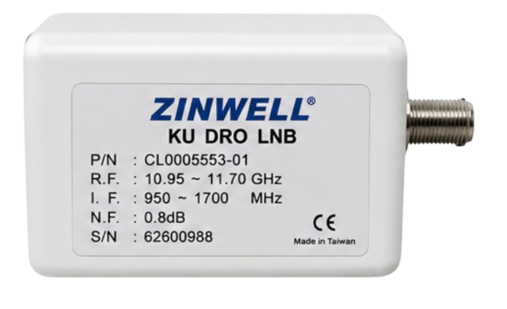
In professional satellite communication systems, the Low Noise Block Downconverter (LNB) is one of the most important components in the receive chain. Installed at the antenna feed, an LNB receives a high-frequency satellite signal, amplifies it while minimizing additional noise, and converts it to a lower intermediate frequency (IF) that can be transported through coaxial cable to the satellite receiver or modem.
The ZK-VE1 10.95–11.70 GHz Ku-Band DRO LNB, manufactured by Zinwell Corporation, is a dedicated Ku-band LNB designed for satellite reception applications. According to the supplied product documentation, the ZK-VE1 operates across the 10.95–11.70 GHz input frequency range and converts the received signal to an 950–1700 MHz output frequency range using a 10 GHz local oscillator.
With a typical 1.0 dB noise figure, 50–60 dB conversion gain, ±1 MHz local oscillator frequency stability across -40°C to +60°C, and an operating temperature range extending from -40°C to +60°C, the ZK-VE1 is designed as a practical RF front-end solution for Ku-band satellite reception.
For customers looking for this type of Ku-band LNB for satellite communication installations, VSATPlus can provide the ZK-VE1 and assist with sourcing and ordering requirements.
The ZK-VE1 is a Ku-band DRO LNB designed to receive satellite signals in the 10.95–11.70 GHz frequency range.
The term LNB stands for Low Noise Block Downconverter. Its primary functions are:
The ZK-VE1 uses a 10 GHz local oscillator (LO). Based on the specified input and output frequencies, the LNB converts the incoming Ku-band signals into the 950–1700 MHz IF range.
This makes the unit suitable for integration into satellite antenna systems where the receiver or modem expects an L-band/IF signal rather than the original high-frequency Ku-band signal.
The supplied documentation identifies the product as:
10.95–11.70 GHz Ku Band DRO LNB: ZK-VE1
and lists Zinwell Corporation as the manufacturer. The specification sheet is dated October 16, 2001, with the note that specifications are subject to change without notice.
One of the defining characteristics of the ZK-VE1 is its dedicated Ku-band operating range.
The specified input frequency range is:
10.95–11.70 GHz
This means the LNB is designed to receive satellite carriers located within this portion of the Ku-band spectrum.
Unlike universal Ku-band LNBs that cover multiple Ku-band sub-ranges, the ZK-VE1 is designed around a specific frequency range. Therefore, system designers and installers should verify the satellite transponder frequency before selecting the LNB.
The corresponding output frequency range is:
950–1700 MHz
This lower-frequency signal can then be transported over the coaxial connection to compatible receiving equipment.
The ZK-VE1 uses a:
10 GHz Local Oscillator
The local oscillator is a fundamental part of the frequency-conversion process.
For example, a received RF signal at the upper end of the specified range can be converted into an IF signal by subtracting the local oscillator frequency. The specified 10 GHz LO therefore provides the frequency translation required to transform the 10.95–11.70 GHz satellite signal into the 950–1700 MHz output range.
The use of a fixed 10 GHz LO also makes the ZK-VE1 a relatively straightforward component to integrate when the satellite frequency plan is known.
Noise performance is particularly important in satellite reception because signals arriving at the antenna can be extremely weak.
The ZK-VE1 specifies:
Noise Figure: 1.0 dB typical
A low noise figure means the LNB adds relatively little noise to the received signal.
This is important because the LNB sits at the front end of the receive chain. Any additional noise introduced at this stage can affect the overall system noise performance.
With its specified 1.0 dB typical noise figure, the ZK-VE1 is designed to provide low-noise amplification for its intended Ku-band operating range.
For satellite system engineers, the LNB’s noise figure should be considered together with antenna gain, satellite EIRP, atmospheric losses, cable losses, receiver performance, and the overall link budget.
The specification sheet gives the ZK-VE1 a conversion gain range of:
50–60 dB
Conversion gain represents the amplification provided while the received RF signal is converted to the lower IF frequency.
The relatively high gain range allows the LNB to compensate for losses that can occur between the antenna feed and the indoor satellite receiving equipment.
However, the required gain in a complete system depends on factors such as:
The ZK-VE1 therefore needs to be evaluated as part of the complete RF chain rather than as an isolated component.
The supplied specifications also provide detailed information about gain consistency.
The specified gain variation is:
±3 dB over any 30°C temperature range
The datasheet also specifies gain flatness as:
These specifications provide useful information about how consistently the LNB maintains its gain across frequency and changing temperature conditions.
For satellite communication system designers, gain flatness can be important when dealing with wider-band signals or multiple carriers because significant gain variation across the operating bandwidth can affect signal levels reaching the receiver.

Frequency stability is another important characteristic of an LNB.
The ZK-VE1 specifies:
L.O. Frequency Stability: ±1 MHz
over an operating temperature range of:
-40°C to +60°C
This specification describes the maximum stated variation of the local oscillator frequency across the specified temperature range.
Stable local oscillator performance helps maintain predictable frequency conversion between the satellite RF input and IF output.
This is particularly relevant for outdoor satellite installations because the LNB may be exposed to significant temperature changes during normal operation.
The ZK-VE1 specification sheet provides phase-noise values at three frequency offsets.
| Offset | Phase Noise |
|---|---|
| 1 kHz | -65 dBc/Hz |
| 10 kHz | -75 dBc/Hz |
| 100 kHz | -90 dBc/Hz |
Phase noise describes unwanted short-term frequency fluctuations around the local oscillator frequency.
In satellite communication systems, LO phase noise can be an important consideration because excessive phase noise may affect the quality of frequency conversion and the performance of the receiving system.
The values provided by the manufacturer allow system designers to evaluate the ZK-VE1 against the phase-noise requirements of their specific satellite application.
The datasheet specifies:
Output Power at 1 dB Gain Compression Point: 0 dBm minimum
The 1 dB compression point is an important RF characteristic because it indicates the approximate output level at which the device’s gain begins to depart from its linear behavior.
For satellite system integration, this specification helps engineers understand the signal-handling capability of the LNB and evaluate whether the output level is appropriate for the connected receiving equipment.
The actual operating point should always be considered together with the input signal level and the requirements of the downstream receiver.
The RF input interface of the ZK-VE1 is specified as:
WR-75
The WR-75 waveguide is commonly associated with Ku-band antenna/feed assemblies.
The waveguide provides the RF connection between the antenna/feed system and the LNB’s receiving section.
For installers, matching the LNB’s waveguide interface with the antenna feed assembly is essential for correct mechanical and RF integration.
The ZK-VE1 uses an:
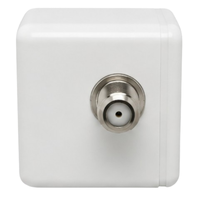
F-Type, Female
output connector.
The output carries the converted IF signal in the 950–1700 MHz range.
This allows the LNB to be connected to a compatible satellite receiver or modem using an appropriate coaxial cable.
The F-type interface is a familiar connection method in satellite receiving systems and makes the ZK-VE1 straightforward to integrate into compatible RF installations.
The following table summarizes the specifications provided in the supplied Zinwell product document.
| Specification | ZK-VE1 |
|---|---|
| Product Type | Ku-Band DRO LNB |
| Input Frequency Range | 10.95–11.70 GHz |
| Output Frequency Range | 950–1700 MHz |
| Local Oscillator Frequency | 10 GHz |
| Input Waveguide Flange | WR-75 |
| Conversion Gain | 50–60 dB |
| Gain Variation | ±3 dB over any 30°C |
| Gain Flatness | ±1 dB p-p @ 54 MHz |
| Gain Flatness | 4 dB p-p @ 750 MHz |
| Noise Figure | 1.0 dB typical |
| Output Power at 1 dB Compression | 0 dBm minimum |
| LO Frequency Stability | ±1 MHz (-40°C to +60°C) |
| Phase Noise @ 1 kHz Offset | -65 dBc/Hz |
| Phase Noise @ 10 kHz Offset | -75 dBc/Hz |
| Phase Noise @ 100 kHz Offset | -90 dBc/Hz |
| Output Return Loss | 7.5 dB minimum |
| Output Connector | F-Type Female |
| DC Supply Voltage | 11.5–24 V |
| DC Current Consumption | 150 mA maximum |
| Operating Temperature | -40°C to +60°C |
| Manufacturer | Zinwell Corporation |
| Product Model | ZK-VE1 |
| Documentation Revision Date | October 16, 2001 |
All values in the table above are taken directly from the supplied product specification document.
The ZK-VE1 operates from a DC supply range of:
11.5–24 V
The maximum specified current consumption is:
150 mA
This provides a relatively straightforward power requirement for compatible satellite receiving equipment.
Before installation, the installer should verify that the connected receiver, modem, or external power source can provide the required voltage and current.
Correct DC powering is particularly important for outdoor RF equipment because the LNB must operate continuously while maintaining its specified frequency-conversion and amplification functions.
The ZK-VE1 is specified for operation between:
-40°C and +60°C
This wide temperature range is valuable for outdoor satellite installations where the equipment may experience significant temperature changes.
The frequency-stability specification is also explicitly given over this same temperature range, with the LO stability specified at ±1 MHz.
For system deployment, the environmental requirements of the complete antenna and RF assembly should still be evaluated rather than considering the LNB independently.

The specified output return loss is:
7.5 dB minimum
Output return loss provides information about impedance matching at the IF output interface.
Good impedance matching is important for minimizing reflections and ensuring effective signal transfer between the LNB and the connected coaxial transmission system.
When integrating the ZK-VE1 into a larger RF system, the output return-loss specification can therefore be considered alongside cable characteristics, connector quality, receiver input impedance, and other components in the IF chain.
The primary application of the ZK-VE1 is Ku-band satellite signal reception within its specified 10.95–11.70 GHz input range.
The LNB can form part of an antenna’s outdoor receive assembly, converting the incoming satellite signal to the 950–1700 MHz IF range required by compatible downstream equipment.
The ZK-VE1 can be considered for compatible Ku-band VSAT architectures where the satellite carrier frequencies fall within the LNB’s specified input range.
In such systems, the antenna receives the satellite signal, the ZK-VE1 performs low-noise amplification and frequency conversion, and the resulting IF signal is delivered through coaxial cable to the receiving equipment.
The device can also be considered for satellite ground-station receive chains that require a Ku-band LNB matching the specified RF and IF characteristics.
System designers should confirm frequency compatibility, receiver requirements, power requirements, waveguide interface, and complete link-budget requirements before deployment.
The -40°C to +60°C operating specification makes the product suitable for consideration in outdoor environments with substantial temperature variation, provided that the complete installation meets the environmental requirements of the application.
Several characteristics make the ZK-VE1 an interesting option for compatible Ku-band receive systems.
The 10.95–11.70 GHz input range provides clearly defined Ku-band coverage for systems operating within this frequency segment.
The low typical noise figure supports low-noise signal reception at the antenna front end.
The specified gain provides substantial amplification between the RF input and IF output.
The fixed 10 GHz LO provides the frequency conversion required to generate the specified 950–1700 MHz IF output.
The -40°C to +60°C specification supports outdoor satellite applications exposed to changing temperatures.
The WR-75 interface provides compatibility with appropriate Ku-band antenna feed assemblies.
The F-type output provides a familiar and practical connection for compatible coaxial IF systems.
The manufacturer provides phase-noise specifications at 1 kHz, 10 kHz, and 100 kHz offsets, giving system designers useful RF performance information.
Because the ZK-VE1 is a dedicated Ku-band LNB rather than a universal Ku-band model, frequency compatibility should be one of the first considerations.
Before ordering, customers should verify:
These checks help ensure that the selected LNB is compatible with the complete satellite system.

For customers searching for a Zinwell ZK-VE1 10.95–11.70 GHz Ku-Band DRO LNB, VSATPlus can provide the product and support the sourcing and ordering process.
The ZK-VE1 can be a practical option for satellite operators, system integrators, VSAT installers, telecommunications companies, and other organizations requiring a Ku-band LNB with a defined RF/IF architecture.
When contacting VSATPlus, customers should provide their satellite frequency and receiver/modem requirements so the appropriate configuration can be confirmed before purchase.
For pricing, availability, and ordering information, contact VSATPlus.
The Zinwell ZK-VE1 10.95–11.70 GHz Ku-Band DRO LNB is a dedicated Ku-band low-noise block downconverter designed to receive signals across the 10.95–11.70 GHz frequency range and convert them to a 950–1700 MHz IF output.
Its principal specifications include a 10 GHz local oscillator, 50–60 dB conversion gain, 1.0 dB typical noise figure, 0 dBm minimum output power at the 1 dB compression point, and ±1 MHz LO frequency stability across -40°C to +60°C. The unit also provides defined phase-noise performance, with specifications of -65 dBc/Hz at 1 kHz, -75 dBc/Hz at 10 kHz, and -90 dBc/Hz at 100 kHz offsets.
From an installation perspective, the WR-75 waveguide input, F-Type female output, 11.5–24 V DC supply, and 150 mA maximum current consumption provide the fundamental interfaces required for integration into a compatible satellite receive chain.
Its wide -40°C to +60°C operating temperature range further supports outdoor deployment, while the specified gain variation and gain-flatness characteristics provide additional information for RF system designers evaluating the device.
For satellite professionals looking for a Ku-band DRO LNB matching these specific RF and electrical requirements, the ZK-VE1 is a solution worth considering.
VSATPlus is available to assist customers with sourcing the ZK-VE1, pricing, availability, and ordering. Contact VSATPlus today for more information and to discuss your satellite communication requirements.